GUIDE FOR SETTING UP MPG2/3/4 OVER LPT2 USING MACH3
For this implementation the optional C22 - Pendant Interface Board is required. This board takes power from the USB port for powering the Pendant's circuit and also buffers all the signals to ensure reliable operation. The board also has a relay for wiring a disable circuit at hardware level.
This setup and brains is for an MPG4, but can be used for for an MPG2. The only difference between MPG2 and MPG4 is that MPG4 has more wires and connections for 5th and 6th axis.
It is recommended that you upgrade Mach3 to at least version: Mach3 R3.042.038. On previous versions there could be an axis run-away problem if jogging is disabled while an axis is moving.
The C22 board does the following pin conversion:
|
MPG2 PIN |
WIRE COLOR |
CONNECTION TO: |
I/O |
LPT2 |
MACH3 I/O * |
FUNCTION |
|
|
1 |
Red |
USB +5V |
|
|
|
Encoder +5vdc |
|
|
2 |
Black |
USB GND |
|
|
|
Encoder GND |
|
|
3 |
Green |
DB25-2 |
I |
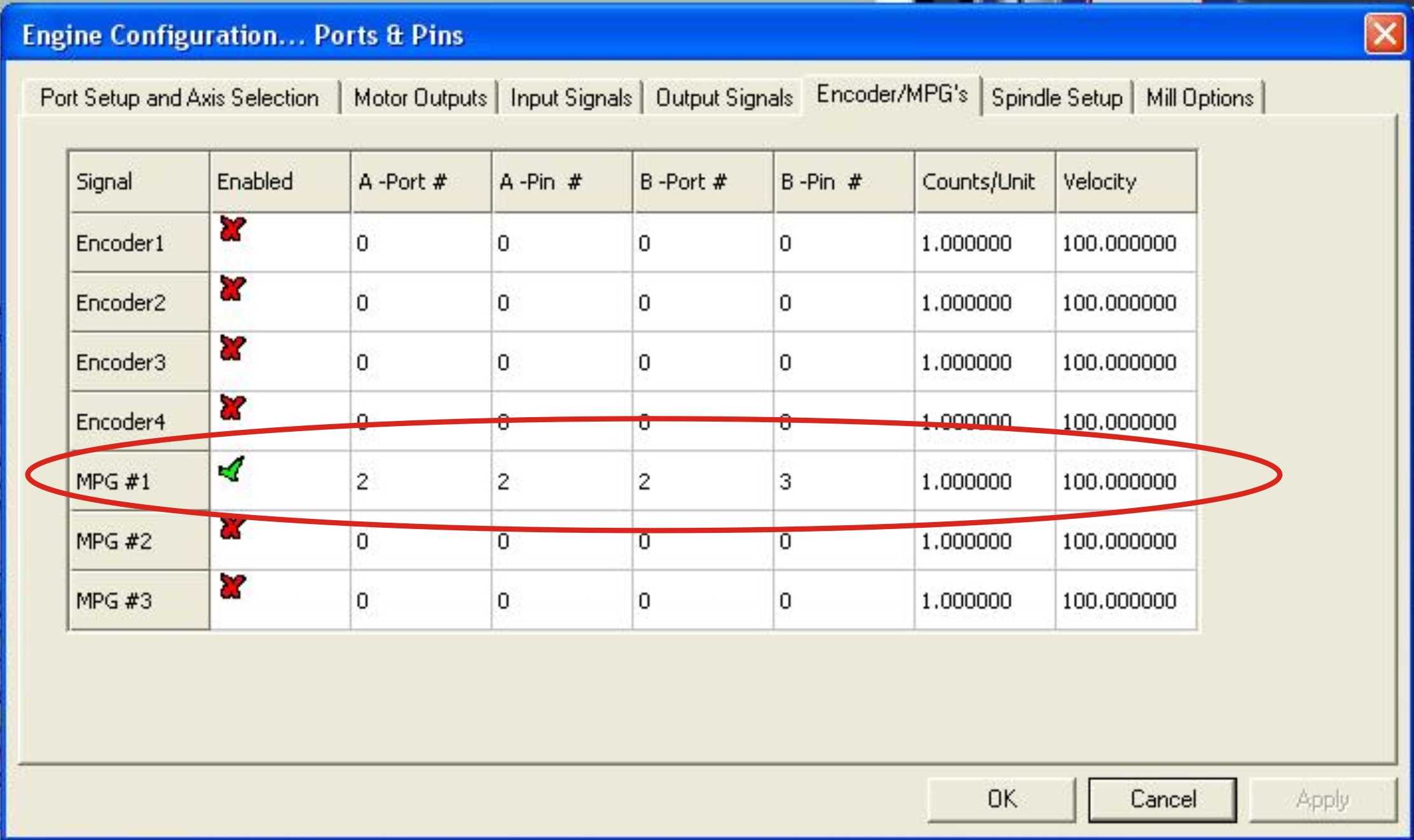
2 |
MPG1-A+ |
MPG CH A+ |
|
|
4 |
White |
DB25-3 |
I |
3 |
MPG1-B+ |
MPG CH B+ |
|
|
5 |
Green/black |
DB25-1 |
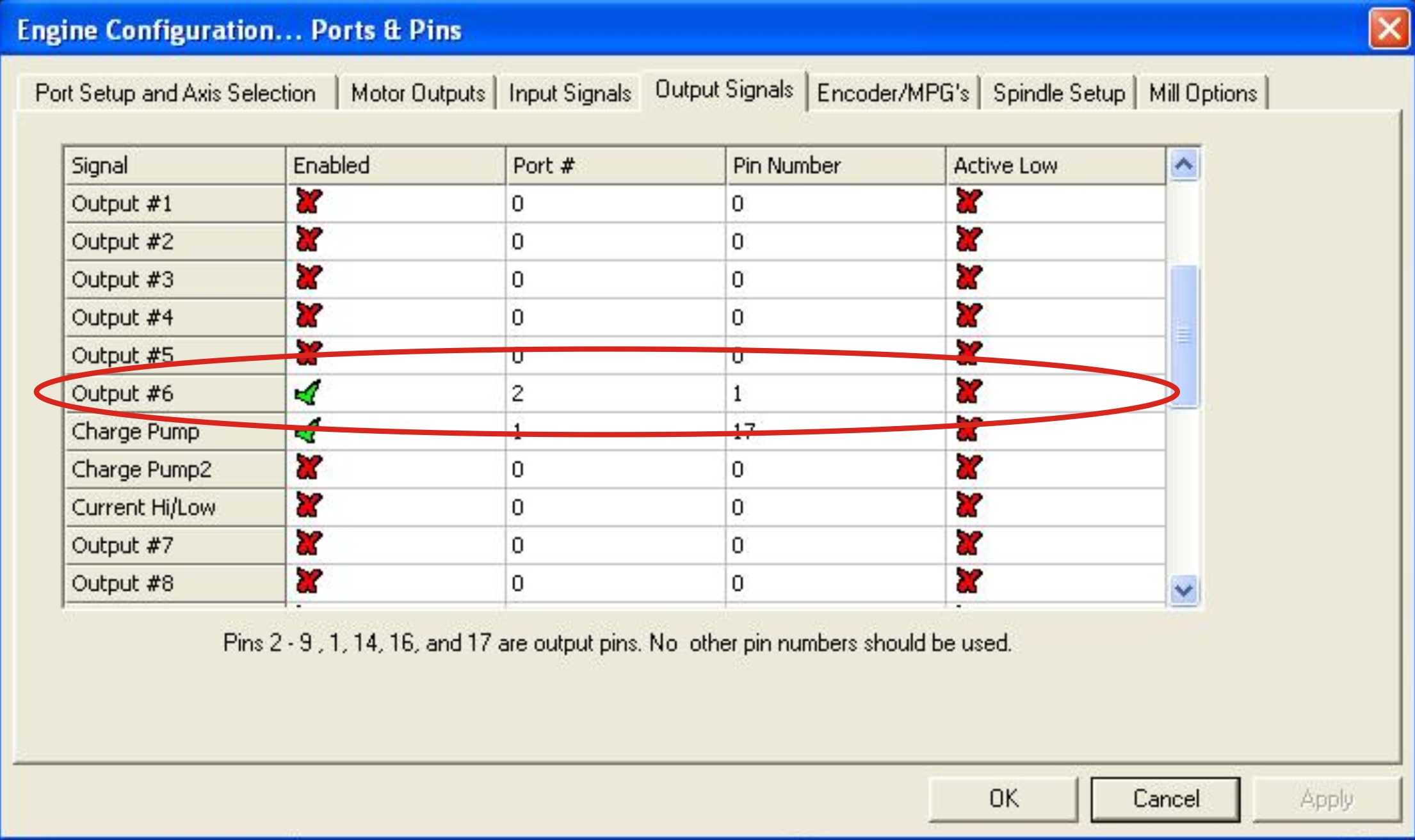
O |
1 |
Output #6 |
Jog “ON” LED +5vdc |
|
|
6 |
White/black |
GND |
|
|
|
Jog “ON” LED GND |
|
|
7 |
Yellow |
DB25-4 |
I |
4 |
OEM Trig #1 |
Select Axis X |
|
|
8 |
Yellow/black |
DB25-5 |
I |
5 |
OEM Trig #2 |
Select Axis Y |
|
|
9 |
|
DB25-6 |
I |
6 |
OEM Trig #3 |
Select Axis Z |
|
|
10 |
DB25-7 |
I |
7 |
OEM Trig #4 |
Select Axis 4 |
||
|
11 |
Gray |
DB25-8 |
I |
8 |
OEM Trig #5 |
X1 |
|
|
12 |
Gray/black |
DB25-9 |
I |
9 |
OEM Trig #6 |
X10 |
|
|
13 |
Orange |
DB25-10 |
I |
10 |
OEM Trig #7 |
X100 |
|
|
14 |
Orange/black |
+5vdc |
|
|
|
COM for Selector switches. |
|
|
15 |
Light blue |
DB25-15 |
I |
15 |
OEM Trig #8 |
E-Stop |
|
|
16 |
Light Blue/black |
+5vdc |
|
|
|
COM for E-Stop. |
|
| 17 | Red/black | ||||||
| 18 | Pink |
DB25-12 |
I |
12 |
OEM Trig #9 |
Select Axis 5 |
|
| 19 | Pink/black |
DB25-13 |
I |
13 |
OEM Trig #10 |
Select Axis 6 |
|
| 20 | Purple | DB25-20 | I | 20 | MPG1-A- | MPG CH A- | |
| 21 | Purple / Black | DB25-21 | I | 21 | MPG1-B- | MPG CH B- |
* These are the I/O functions selected for the Sample XML and Brain files. Users can reassign this.
Steps for configuring Mach3:
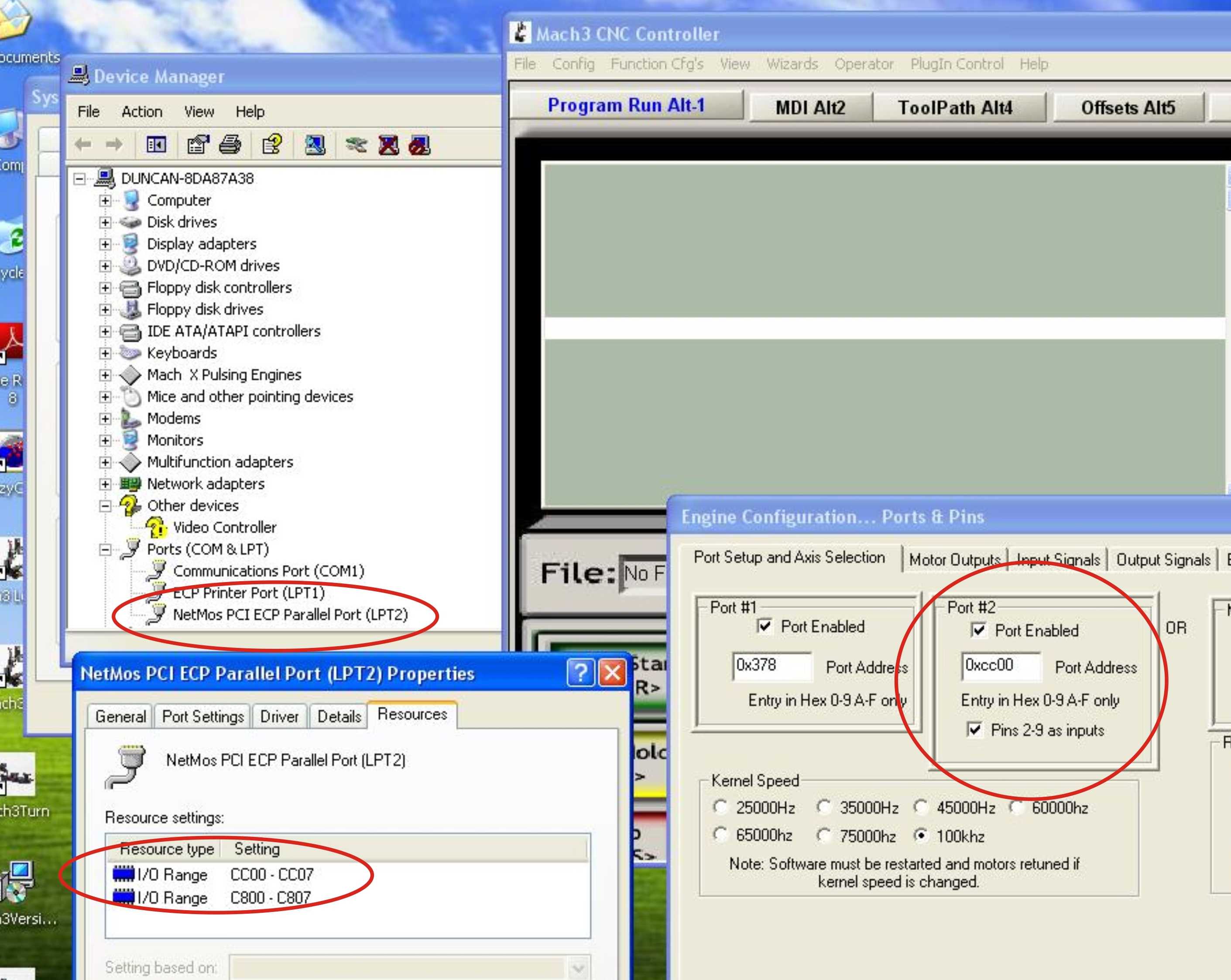
1A. If using parallel ports, install a second parallel port on an available PCI port. If you do not have one, you can source one here: After installing and configuring a parallel port on the second port of the PC, make sure you configure Mach3 to allow that port to be used for input on pins 2-9 and that you have the correct memory address.
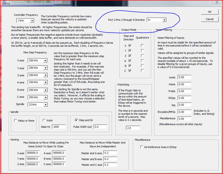
1B. If using the Smooth Stepper, make sure to enable pins 2-9 to work as inputs on LPT2.
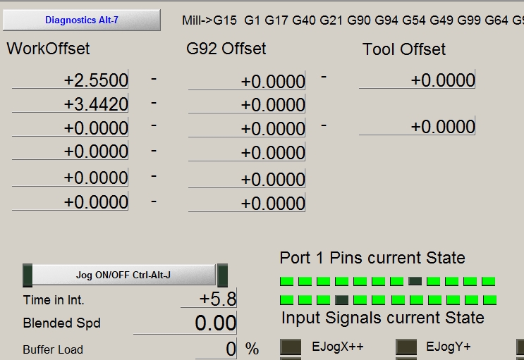
2. Connect the C22 to LPT2, the Pendant to the C22 and power the C22. Go to the diagnostics screen in mach3 and confirm that the Pendant communicates with Mach3 by moving knobs and buttons on the Pendant and watching the LEDs for the status of the pins changing states. Note that is using the C32 board, the C22 is not required as this circuit is included in the board.
3. Configure the Output for the pendant's LED.
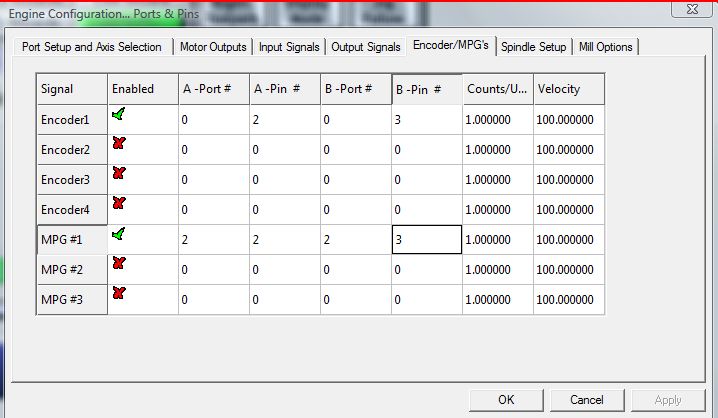
4. Configure the MPG under Ports & Pins.
5. Configure the Input Pins.
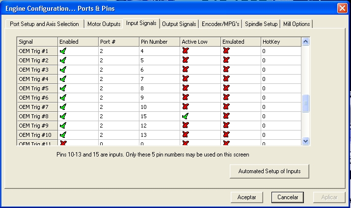
The C23 Rev 2. Inverts input pins 12 and 10.
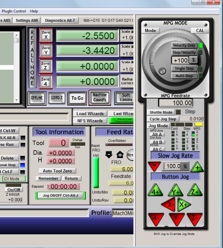
6. Hit the TAB key to bring the JOG window and play with the hand wheel. At this point the buttons on the pendant will not work, but you should be able to calibrate the MPG, move the axis if you select the options manually from the JOG menu.
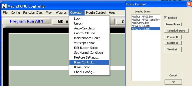
7. Download the Brains file "MPG4_LPT2BrainsV4.zip", extract the files and copy them into: "C:\Mach3\Brains". Then enable the new brains. You should choose between E-Stop with and without auto enable. The one with auto enable will put mach3 out of reset as soon as you pull the e-stop button out. The other one will require that you hit the reset button in the mach3 screen.
- Axis_JogRes_Selector.brn: Handles Axis selection and Jog resolution. It also enables/disables JOG option no axis is or is not selected.
- Enable.brn and Disable.brn: It handles the enable/disable button.
- E-Stop_W_AutoReset.brn: It handles E-STOP. This brain will automatically reset mach3 when the e-stop button is pulled out.
- E-Stop_WO_AutoReset.brn: This Brain handles E-Stop. It requires that the user press the "RESET" button in the screen in order to reset mach3.
Each brain can be enables and run independently. For example the can select which E-STOP brain to use according the what the user prefers to use. Many users prefer not to use the enable button, so they do not need to enable this brain. Having each brain run independently also eases customizing the brains by the users. A sample XML file is also provided.
If you are upgrading from a previous installation, make sure you backup and erase the old brains and do not forget to hit "Reload All Brains".
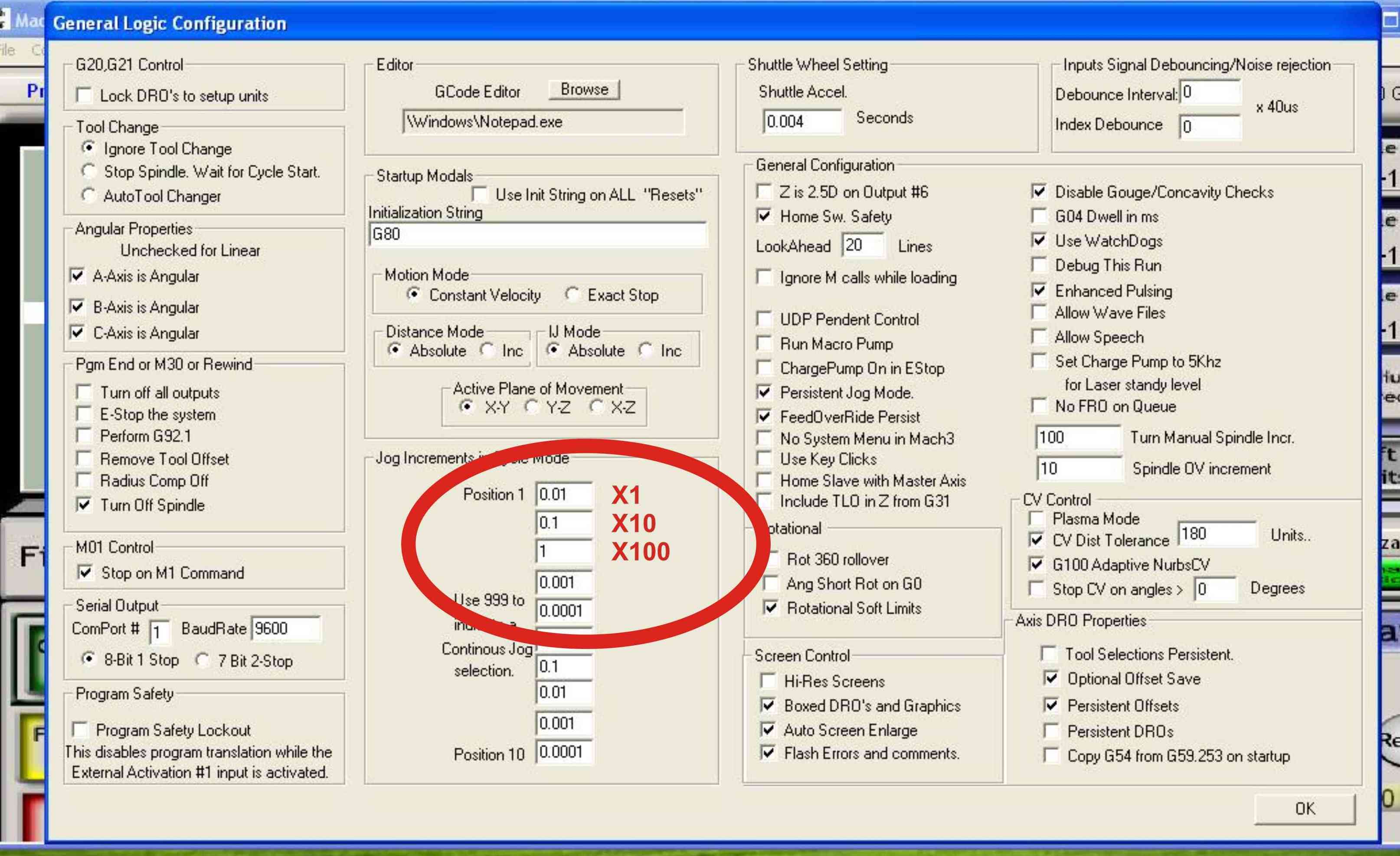
8 Configure the increment to be used under: Config / General Configuration. These will be the increments that will work for the X1, X10, and X100 positions of the jog resolution knob.
An XML file with this configuration can be found HERE:
Brains that allow for using axis 5 and 6 for adjusting Feedrate Override and Spindle Speed can be found HERE : With this brains the pendant will handle axis 1-4 as the other brains, but when axis 5 or 6 are selected, jog will be disabled and the hand wheel will adjust feedrate or spindle speed override. If using these brains, the Encoder1 must also be configured on the same pins as MPG1 but on port 0: