OVERVIEW
This card lets you control your spindle with PWM and direction signals, as if it was an axis motor. It converts the step signal into and an analog (0-10VDC). This card also has two relays that can be used to control the direction (CW/CCW) and enable the drive (On/Off).
A Variable Frequency Drive or Inverter works by modifying the frequency for AC motors. Most of these devices can be controlled with an external analog signal (0-10VDC). That is, if there is 5VDC coming into through the control signal, the motor will run at 50% of full speed, if there was 10VDC, the motor will run at 100% of full speed. If there is no signal coming out, then the motor will stop.
This unit can also be used on many DC motor controllers by replacing the potentiometer that controls the speed.
FEATURES
-
Has two relays that can be used to control the direction and enable and disable the drive.
-
Uses only two pins, one for PWM and one for direction. It is the presence of absence of the valid PWM signal what would start/stop the spindle.
-
Jumper to select mode of operation, US or International mode. On US mode, one relay would be used to start CW and the second one to start CCW. On International mode Relay 1 will start/stop, and Relay 2 will determine the direction of rotation.
-
Optoisolated output signals. The analog and CW/CWW signals are optically isolated, so this board can be used with drives that make grounds common with the mains that drive the VFD or motor.
-
Comes with an RJ45 Connector fast installation. With this connector you just have to plug in an standard RJ45 cable and will not require further wiring.
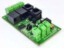
![[C41S] C41S - PWM Variable Speed Control Board.gif](/web/image/product.image/531/image_128/%5BC41S%5D%20C41S%20-%20PWM%20Variable%20Speed%20Control%20Board.gif?unique=e1bfe6e)

![[C41S] C41S - PWM Variable Speed Control Board.gif](/web/image/product.image/531/image_1024/%5BC41S%5D%20C41S%20-%20PWM%20Variable%20Speed%20Control%20Board.gif?unique=e1bfe6e)