
PTS-1 PLASMA TOUCH SENSOR Rev.1
AUGUST 2020
TABLE OF CONTENTS
1.0 OVERVIEW
This card has been designed to detect contact by sensing the interaction between the torch and the plate.
2.0 FEATURES
- Optoisolated input works with signals between 5 to 24VDC or Open collector.
- Status LEDs.
- Electromechanical Relays with NO and NC positions.
- Can be powered with 12V or 24V DC.
- Signals and power connections are fully isolated from the probing input.
- It should be compatible with any plasma system. Instructions and configuration files provided for Mach3, Mach4, and UCCNC.
- Din Rail Support.
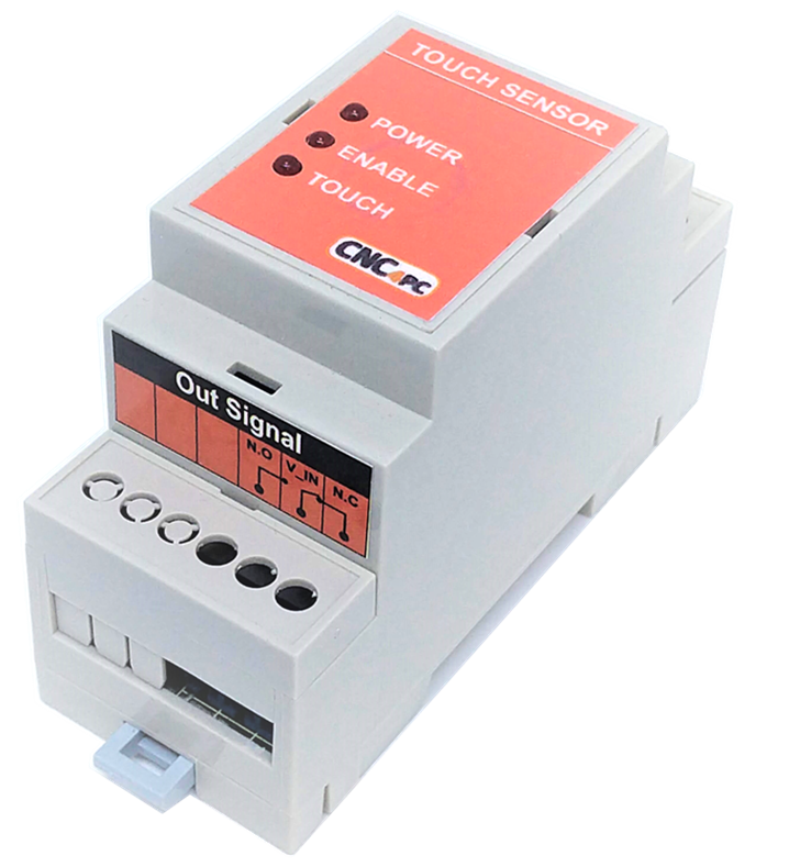
3.0 DESCRIPTION
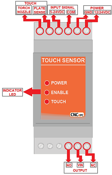
4.0 TERMINAL BOARD
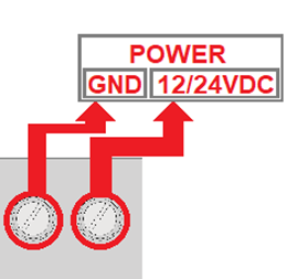
4.1 POWER
Regulated +12VDC to +24VDC at @80mA is required to power this board.
4.2 INPUT SIGNAL
This board supports TTL or Open Collector 5 to 24VDC signals.
Open Collector - Sinking
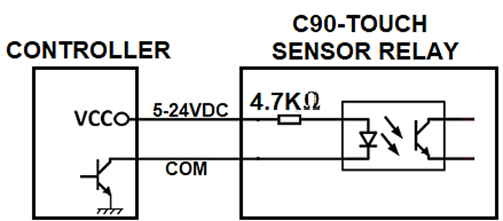
TTL - Sourcing
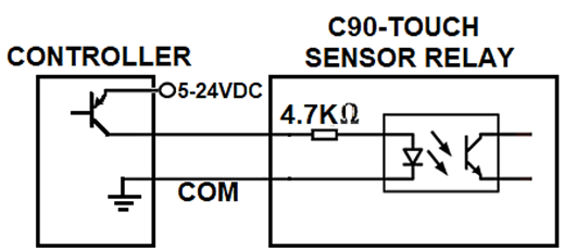
4.3 INTERNAL CIRCUIT
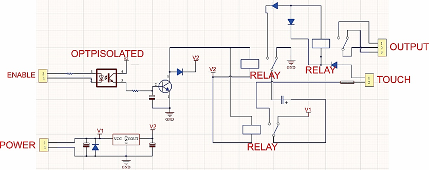
4.4 INPUT SIGNAL TOUCH
The enable signal needs to be active while sensing is
enabled. This is to have the circuit and
relays powered by the capacitor. Once
sensing is complete, the enable should be disabled so the capacitor can be
charged again to be ready for the next sensing sequence.
5.0 PTS-1 Times
5.1 Time to fully charge the capacitors.
5.2 Time that remains active.
6.0 INDICATOR LED
6.1 POWER
Switch on the power supply, and the red LED will light. (Power LED)
6.2 ENABLE
The LED on indicates that it is enabled
6.3 TOUCH
When touched, the red LED will turn on.
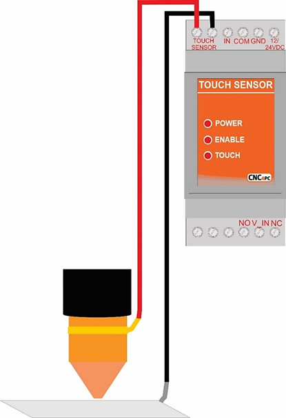
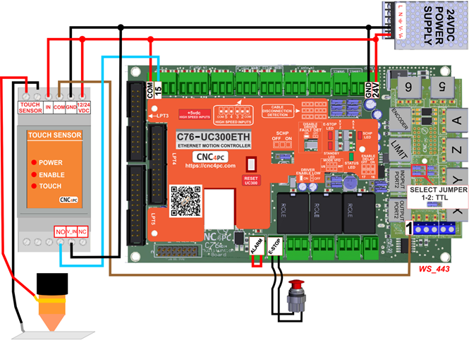
7.0 WIRING SAMPLE
WIRING
SAMPLE WITH C76 TTL
WIRING SAMPLE WITH C25XP
