
THC-2 – TORCH
HEIGHT CONTROL Rev.5.5
JANUARY 2025
TABLE OF CONTENTS
1.0 OVERVIEW
This module allows for controlling the height of the plasma torch head relative to the workpiece during plasma CNC operation, supporting either raw torch head voltage or an input of 0-10VDC. The ARC OK, UP, and DOWN outputs are isolated.
2.0 FEATURES
- Optoisolated output operating at 5 to 24V DC or open collector.
- Built-in Voltage Divider for connecting to the voltage on the torch, or use the 0-10VDC from a voltage divider on the plasma.
- 10 to 30VDC Power Terminal (+24 Typical).
- Isolated Power Connection.
- Din Rail Mountable.
- Voltage Divided software is adjustable.
- Divided input.
- Status LED.
- Mini-Display. (Optional)
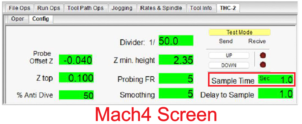
- Screen for Mach4 and UCCNC: On the new screen, all the operating parameters can be adjusted on the fly. NEW
- Macros to update operating parameters for Mach4 and UCCNC: macros that can be run from gcode, you can update parameters on via gcode. So these could be set on the post. NEW
- LEDs on the unit that show TEST MODE, UP, DOWN, ARC OK, and Bluetooth communication. NEW
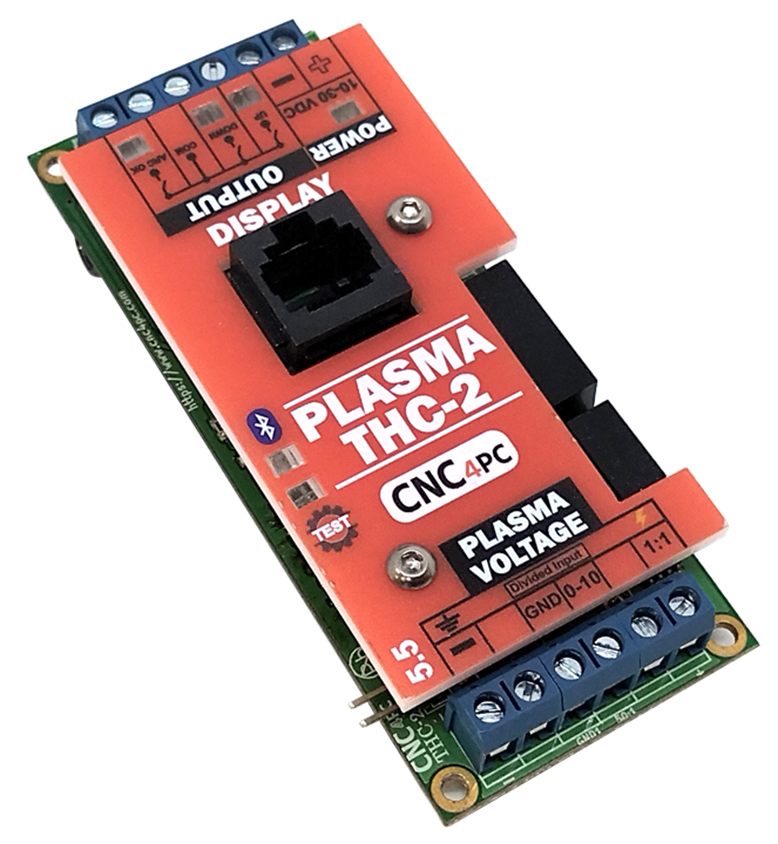
3.0 DESCRIPTION
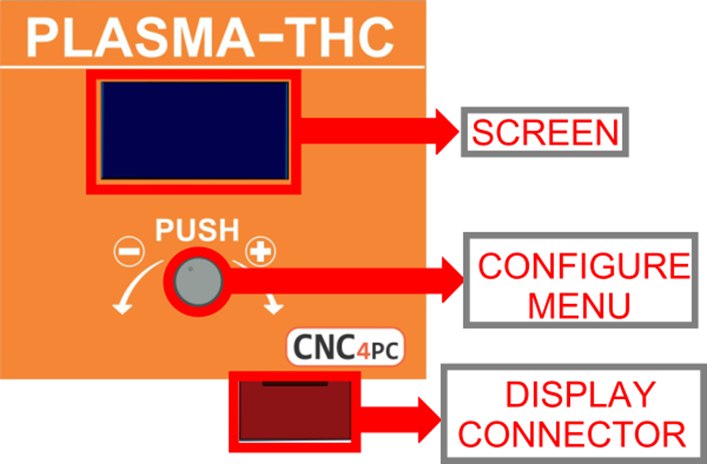
MINI-DISPLAY
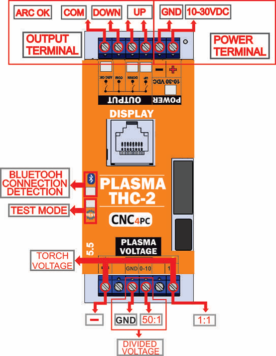
4.0 TERMINAL BOARD
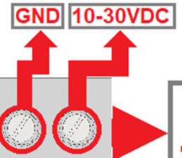
4.1 POWER
Requires a 10 to 30VDC at 100mA Power Supply. Typically, +24vdc are used. “This board is electrically isolated through an internal built-in DC-DC converter.”
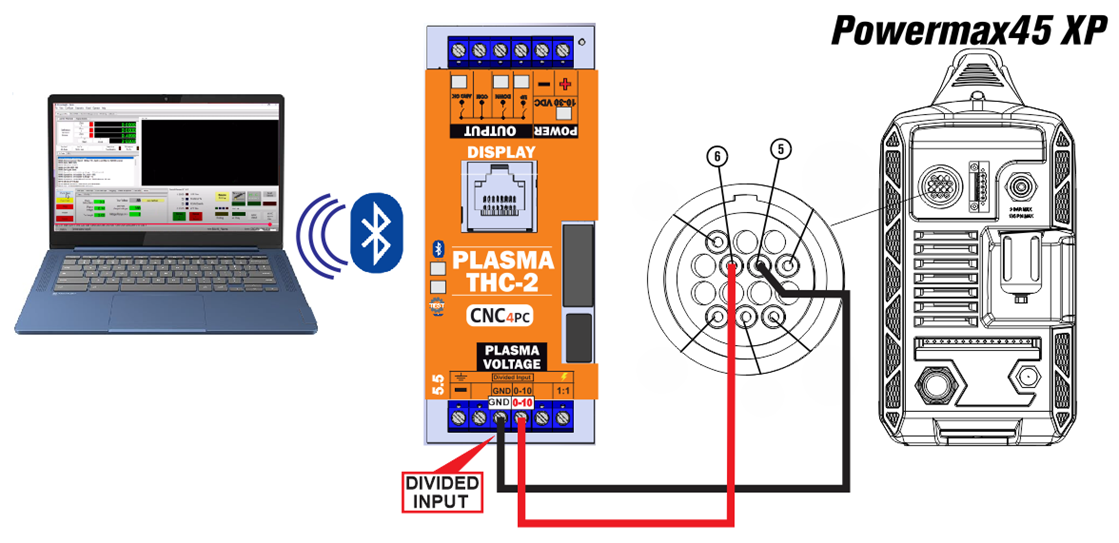
4.2 DIVIDED INPUT
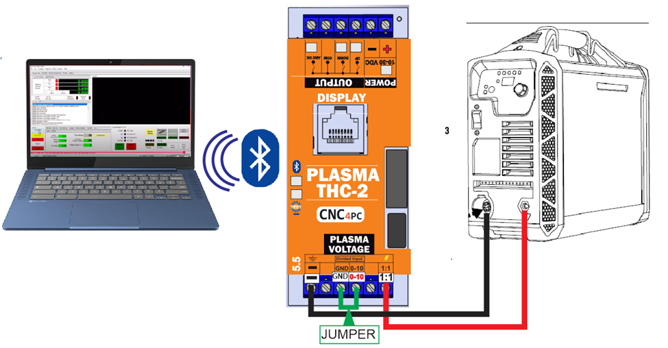
4.3 TORCH VOLTAGE
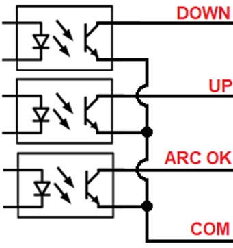
4.4 OUTPUT SIGNALS
Voltage applied can be from 5 to 80VDC@50mA, outputs a signal optoisolated Open Collector.
5.0 CONFIGURE MENU with optional MINI-display.

· Push the knob to enter configuration mode.
· Navigate through the configuration menu by pressing the knob.
· Turn the knob to adjust the value.
· Push the knob to set the value and navigate to the next parameter or until you reach the run mode.
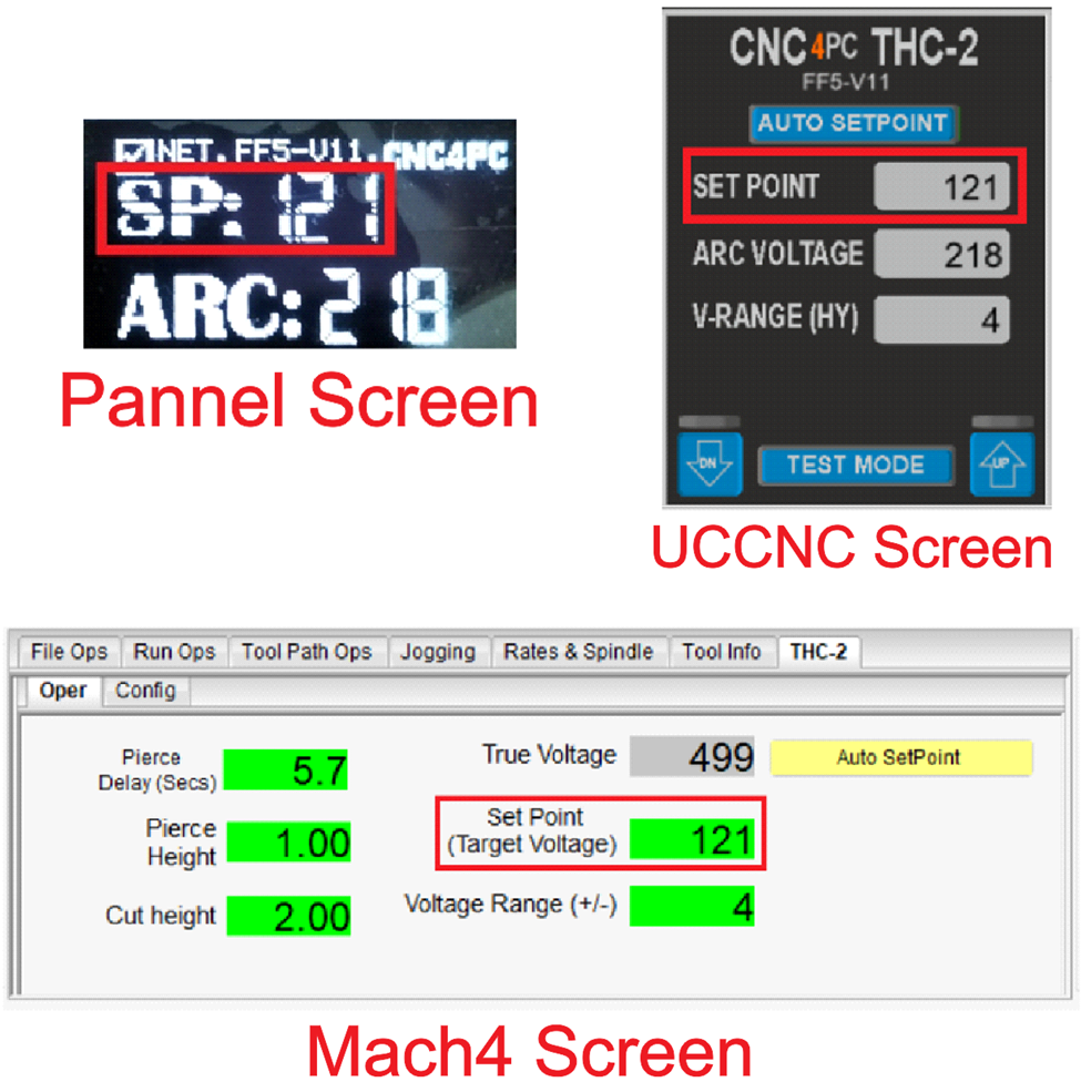
6.0 DESCRIPTION SCREEN
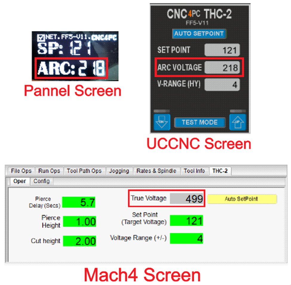
6.1 SET POINT (SP)
Limit from 45 to 255VDC. SP is the target voltage to be achieved.
6.2 VOLTAGE ARC (ARC)
Limit from 40 to 400VDC, True Voltage measured by the THC unit.
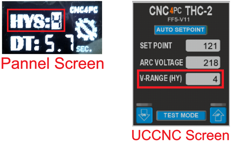
6.3 HYSTERESIS (HYS)
This is the voltage range that you is allowed before sending correction signals. Adjustment signals are sent if the voltage is the hysteresis amount below or above the set point voltage set. If the set point voltage is 100 volts and a hysteresis is set to 2, then DOWN signals will be sent if the voltage reaches 103 volts or above and UP signals sent if the voltage is reaches 97 volts or below. The correction signals are sent until the set point is achieved.

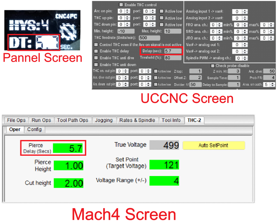
6.4 DELAY TIME (DT)
Torch motion starts the number of seconds you set as DT after the ARC signal is determined. This can be a value between 0.1 to 9.9 seconds.
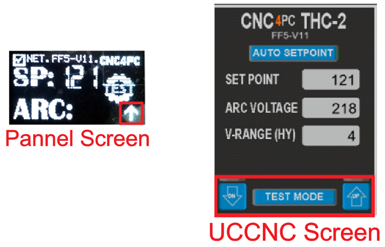
6.5 TEST MODE (TEST)
- Press the knob four times to enter test mode.
- Turn the knob up or down to make the spindle move.
- To exit test mode, press the knob once.

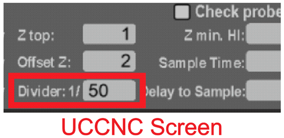
6.6 DIVIDED VOLTAGE CONFIGURATION
- Press the knob three times to enter the setting mode
- Turn the knob to adjust the value.
- Press the knob to set the divided voltage to be set.
- This setting can also be used to fine-tune the voltage read.

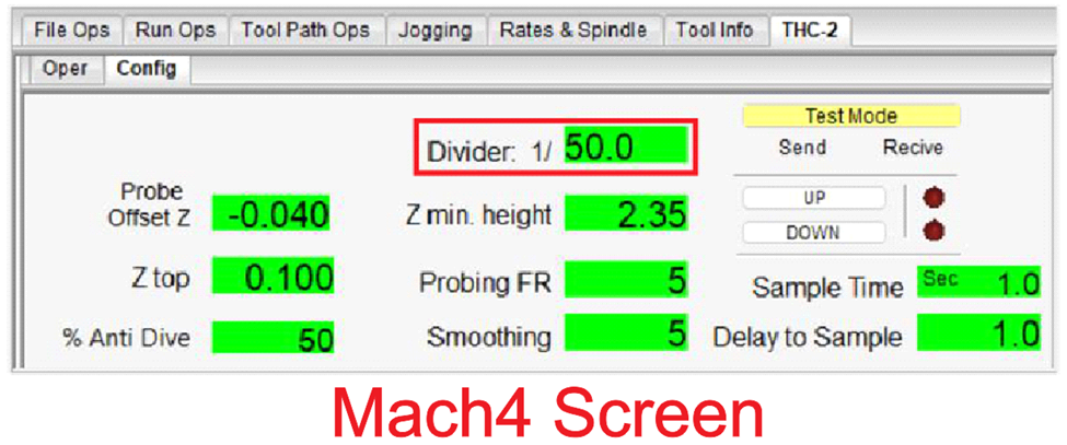
6.6 ANALOG SMOOTING
This data smoothest the voltage reading. This can be a value between 1 to 200. The analog voltage can be noisy or jumpy. This setting will allow for a more stable reading.
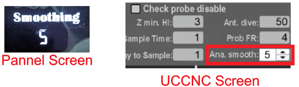

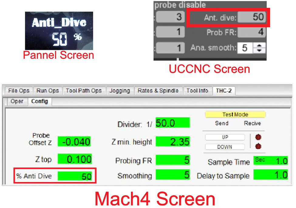
6.7 ANTI-DIVE
If the plasma
torch moves over space, the THC will see it as a voltage spike.
Setting a max value will allow the THC to ignore the voltage spike and prevent
the torch from dying. This can be a value between 10 and 100 %.
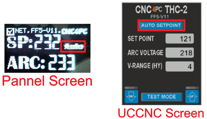
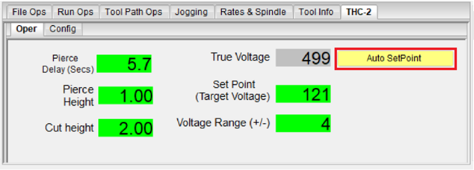
6.8 AUTO_SETPOINT
Automatically establishes the Set Point based on the cutting height that is set. The set point is calculated by measuring the true voltage for a couple of seconds after the delay time (when it starts cutting, then setting this voltage as the set point or target voltage.
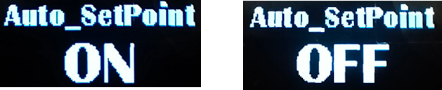
ACTVATE DISABLE
If Auto_SetPoint is activated, the set point adjustment is disabled and the word Auto is displayed on the screen.
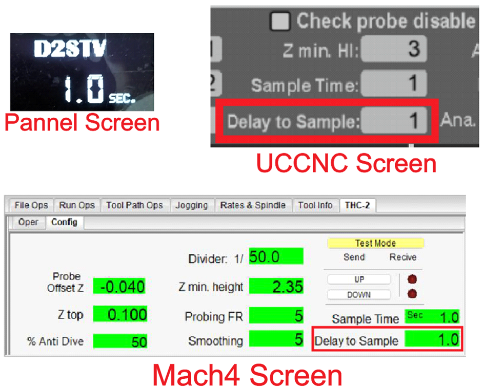
6.9 DELAY TO SAMPLE TARGET VOLTAGE (D2STV)
When using the Auto
Set Point option, you can configure a delay before starting to take the sample
reading. This to allow for the torch
voltage to become stable when it starts cutting.
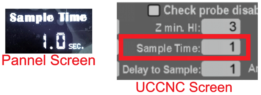
6.10 SAMPLE TIME
This is the time that is going to take to read the voltage that is going to be used to determine the Auto Set Point.
![]() 6.11 CONNECTION
6.11 CONNECTION
When communication between the device and the software is established, a check mark will be displayed on the display panel.

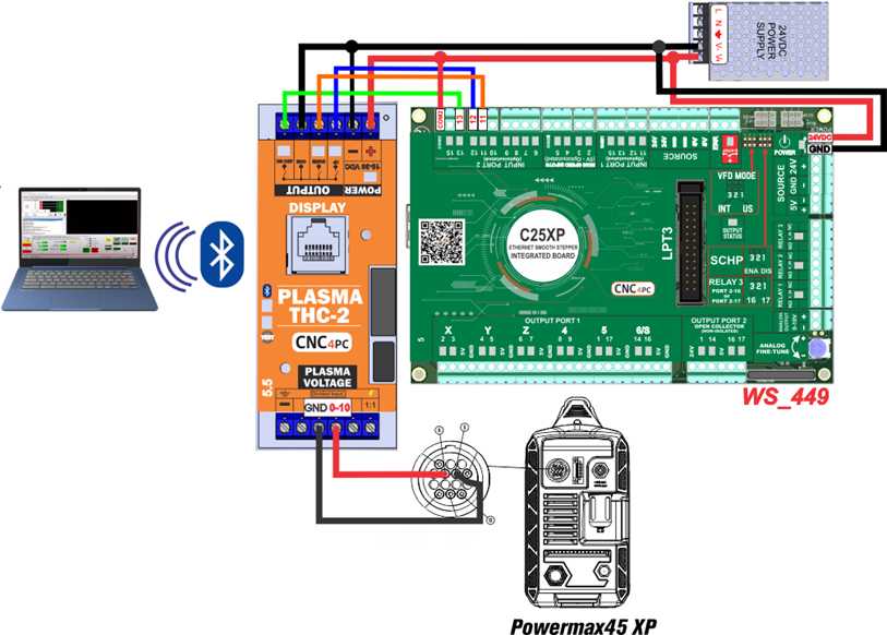
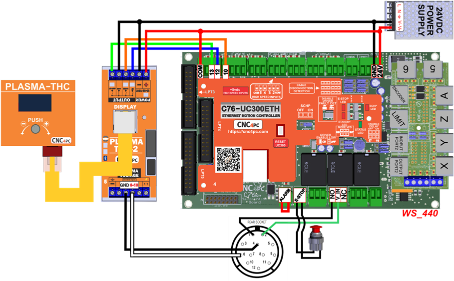
7.0 WIRING SAMPLE
7.1 Wiring C25XP Rev.5.1 and THC-2 Rev.5.5 with Plasma Powermax45 XP
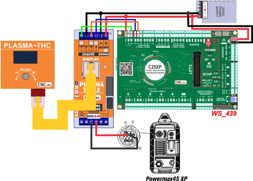
7.2 Wiring C25XP Rev.5.1 and THC-2 Rev.5 with Mini-Display
7.3 Wiring C76 and THC-2 Rev.5 with Plasma Everlast 102i
8.0 DIMENSIONS
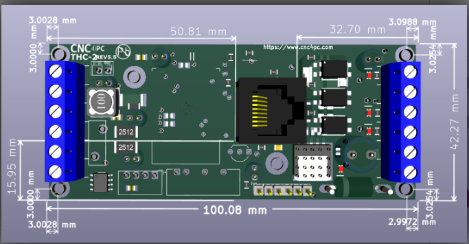
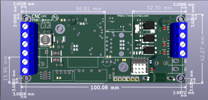
All dimensions are in Millimeters.
Fixing holes (4mm)