
C82- MULTIFUNCTION CNC BOARD
Rev. 5
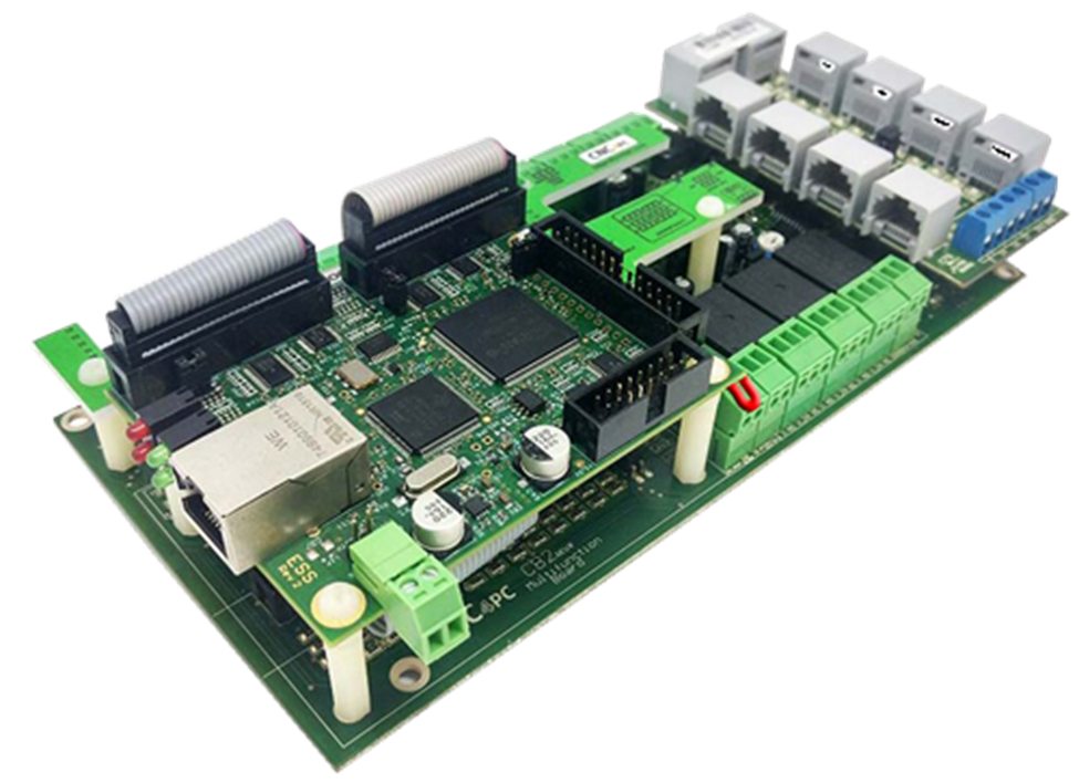
OCTOBER 2024
![]() 1.0 FEATURES
1.0 FEATURES
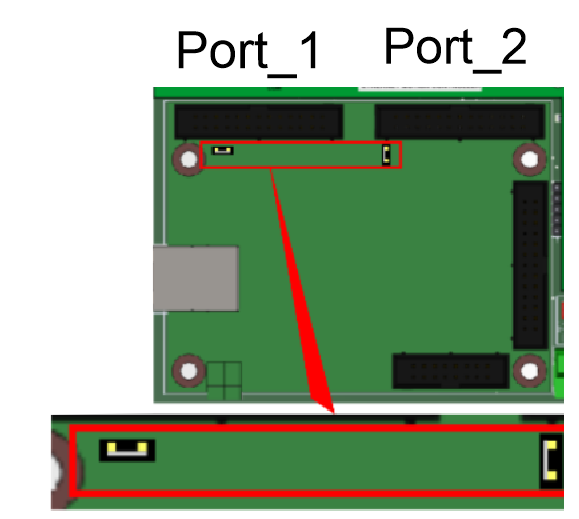
- Designed for ESS AND ETHER-MACH motion controller.
- Built-in PWM-Based Speed Control and Two Built-in Electromechanical Relays with NO and NC positions for spindle control.
- The system monitors:
- E-Stop.
- Safety Charge Pump.
- VFD Fault.
- Driver Fault. - Optoisolated inputs working at 5-24VDC.
- Outputs can be 500mA open collector or +5Vdc at 50mA TTL.
- Buffered outputs.
- Electromechanical Relay with NO and NC positions for general purpose (Port_2 16 or 17, jumper-selectable).
- Microcontroller-based SCHP.
- Can be powered with a voltage of +24VDC.
- Status LEDs on all input and Output connections.
- DIN Rail mountable.
- Pluggable Screw-On Terminals.
- It is compatible with the family of C34 connector boards, which allow for quick connection to popular drives. This compatibility enables not only the step and direction signals but also the fault and enable signals.
- High-speed input.
-
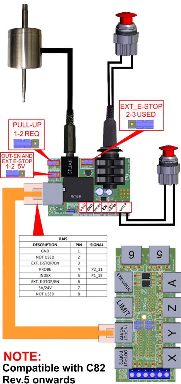
Compatibility with C48Rev.3.5 - EXT_E-STOP *NEW
2.0 I/O SPECIFICATIONS
OPTOISOLATED DIGITAL INPUT TTL SPECIFICATIONS
|
On-state voltage range |
5 to 24VDC |
|
Maximum off-state voltage |
0.8V |
|
Typical signal delay |
2.8uS |
DIGITAL OUTPUT TTL SPECIFICATIONS
|
Maximum output voltage |
5VDC |
|
Maximum output current |
24mA |
|
Maximum off-state voltage |
0.44 V |
|
Maximum supported frequency |
400KHz |
|
Typical signal delay |
10nS |
|
Time of transition to high impedance state |
12nS |
OPEN COLLECTOR OUTPUT SPECIFICATIONS
|
Number of outputs |
4 |
|
Maximum Supported output voltage |
50VDC |
|
Typical output current (general purpose pins) |
500mA |
|
Maximum supported frequency |
250KHz |
|
Typical signal delay |
Less than 8nS |
HIGH SPEED ENCODER INPUT
|
On-state voltage |
5 VDC |
|
Maximum off-state voltage |
0.8V |
|
Typical signal delay |
2.8uS |
|
Rise / Fall Time (Typ) |
50ns - 12ns |
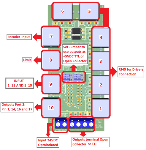
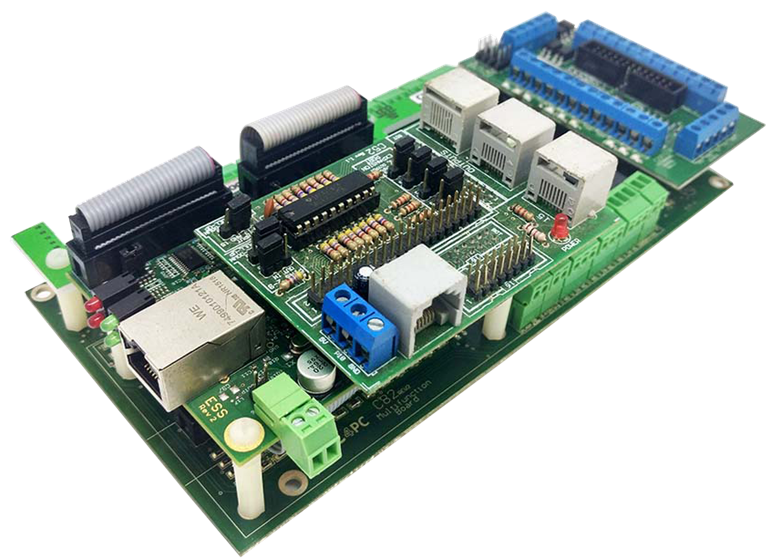
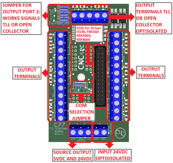
3.0 BOARD DESCRIPTION
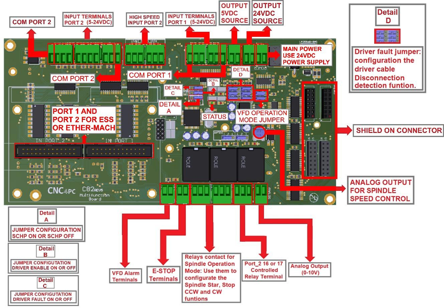
4.0 POWER TERMINALS AND CONFIGURATION JUMPERS
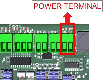
4.1 Power terminal
The board requires an external power supply which can deliver 24VDC@700mA to power the logic of the board and the ESS or ETHER-MACH, but keep in mind that each output can deliver up to 500mA, and if powering other breakout or relay boards. So, you will need to add all the expected power consumption.
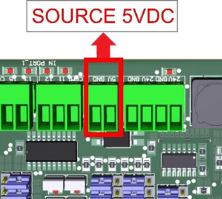
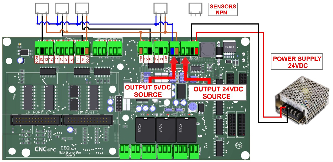
4.2 Source Output 5VDC
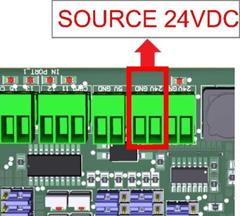
4.3 Source Output 24VDC
10-24VDC can be sourced to sensors or other cards requiring it. Do not exceed 2.5A.
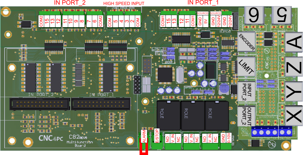
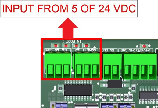
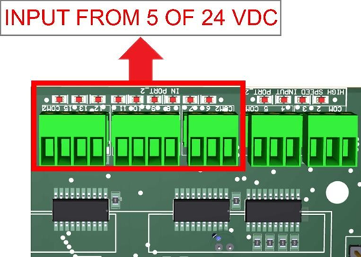
4.4 Input terminals for port_1 and port_2
These terminals support signals 5-24VDC, you can connect sensors NPN, PNP, switches, capacitive sensors, etc.
PORT_1
PORT_2
HIGH SPEED INPUT PORT_2 PIN 2, 3, 4, AND 5
These terminals support signals 5VDC

4.5 Select inputs of port_1 and port_2
COM = 5V
PORT_2 PORT_1
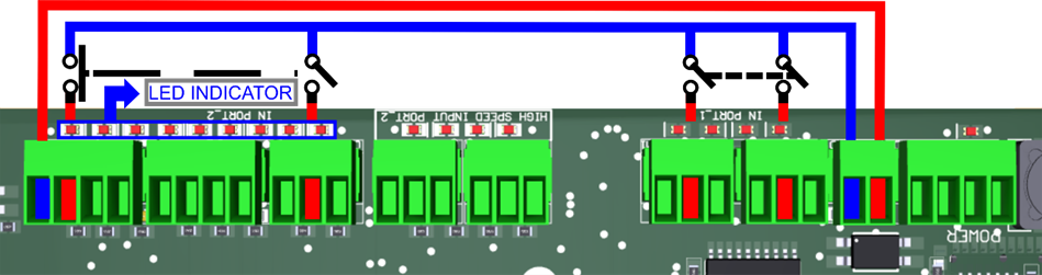
COM = GND with 5VDC
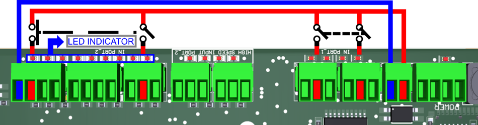
COM = GND with 24VDC
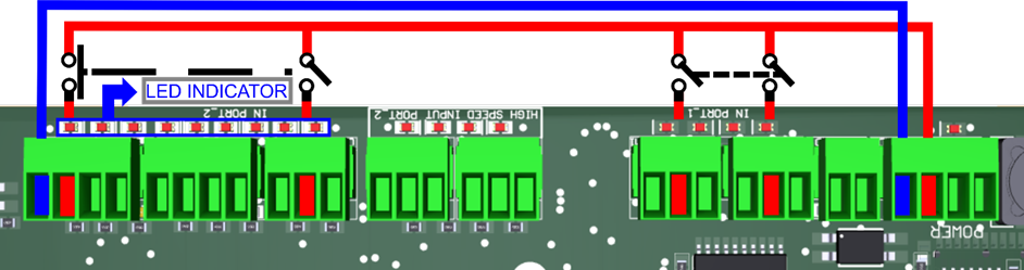
COM = 24VDC
![]() 5.0 JUMPER POSITION
5.0 JUMPER POSITION
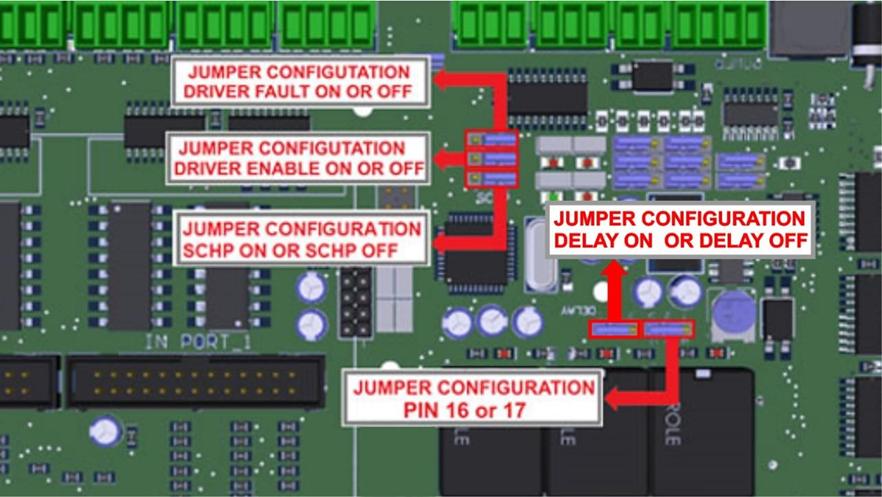
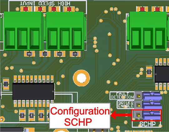
5.1 Selecting the SCHP operation mode
The Safety Charge Pump uses pin 17 on port 2. When the SCHP is enabled on the board, then the output of the terminals will be active while the Safety Charge Pump signal is present and inactive while the SCHP is not present.
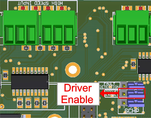
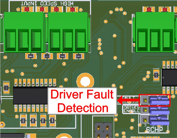
5.2 Driver Enable Jumper
When the Jumper is ON, the C82 sends a low for 5 seconds to enable the driver; if set to OFF, it sends a high for 5 seconds to enable the driver.
5.3 Driver Fault Detection
The Jumper must be on to detect the driver fault.
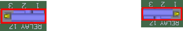
5.4 Configuration jumper pin 16 or 17
Relay can be tied to pin 16 or 17 on port 2.
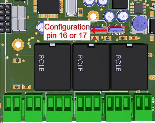
1-2: PIN17 2-3: PIN16
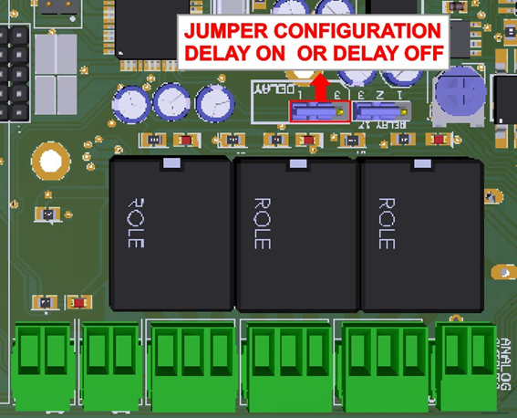
5.5 Configuration jumper pin 16 or 17
When the jumper is selected 1- 2, Delay is enabled.
6.0 CONNECTION EXAMPLE FOR SHIELD C78
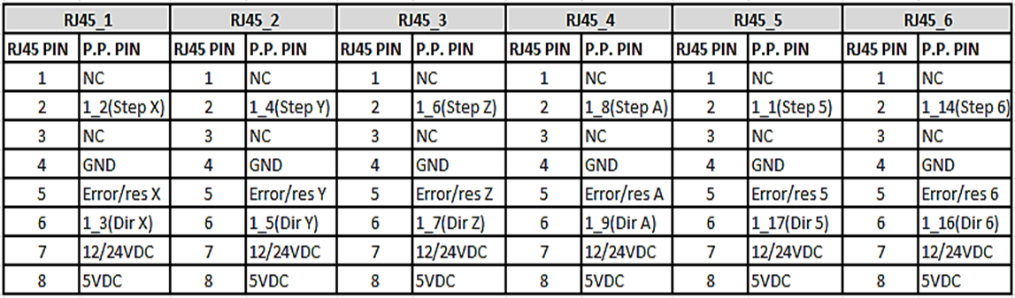
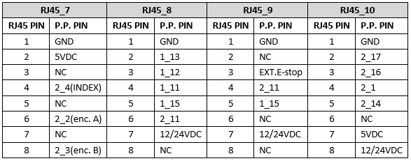
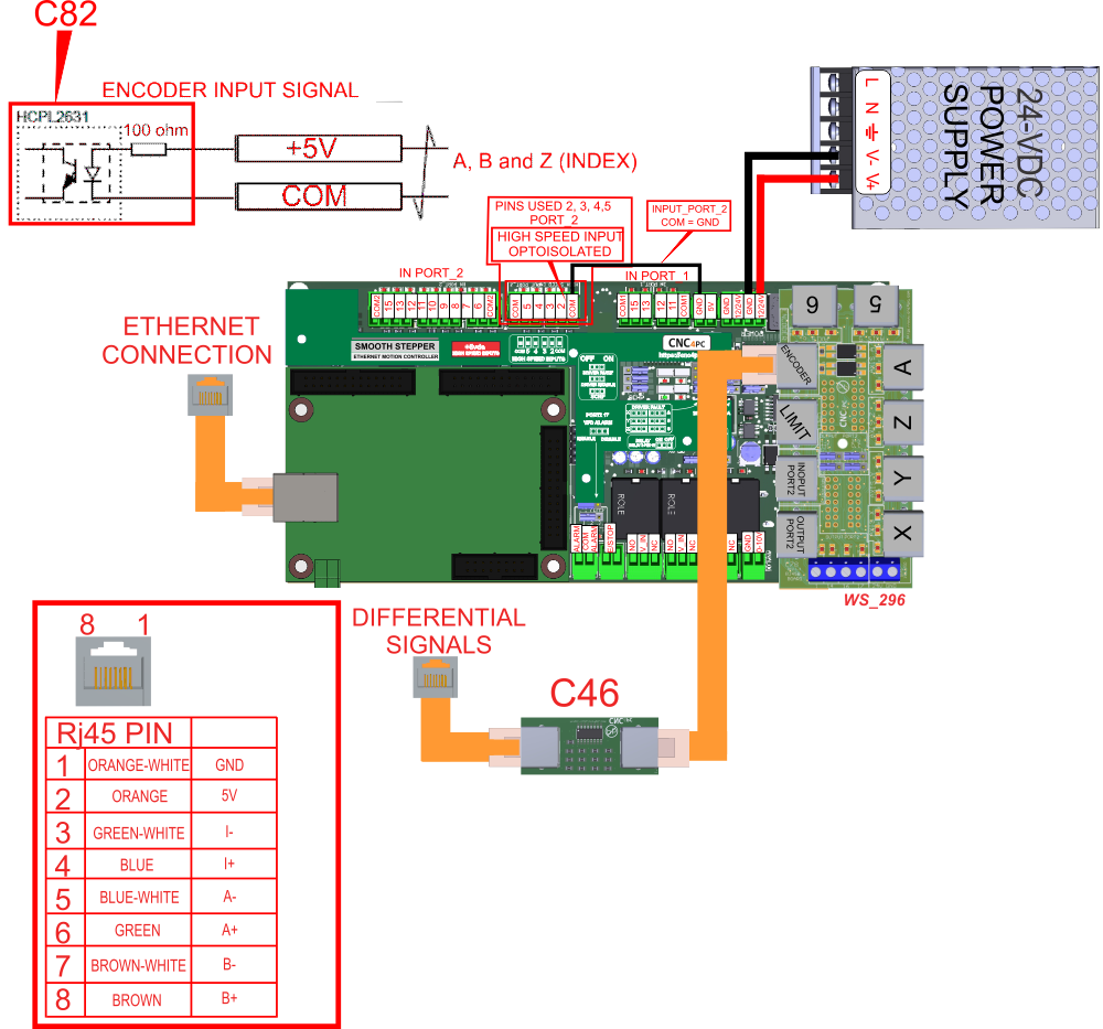
6.1 RJ45 shield C78 connection for axes, Limits and Encoder

6.2 RJ45 shield board description
6.3 Pinout

RJ45 Distribution
7.0 CONNECTION EXAMPLE FOR SHIELD C77
7.1 Terminal Shield Screw-on
7.2 Shield board description
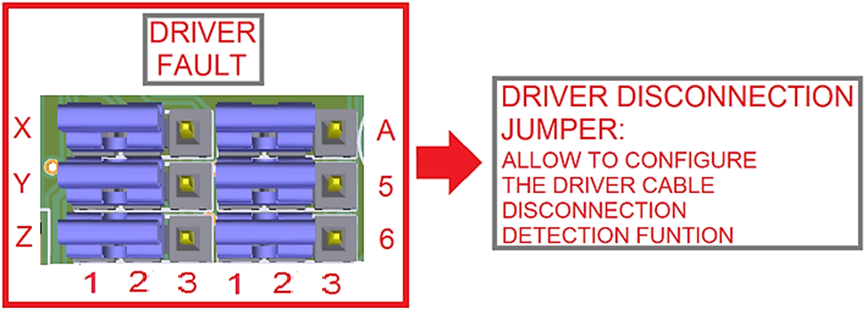
8.0 DRIVER DISCONNECTION JUMPERS
![]() 9.0 E-STOP TERMINAL
9.0 E-STOP TERMINAL
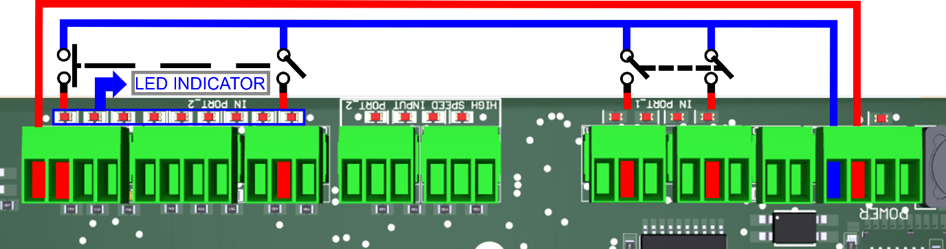
Connect an E-STOP push button as shown in the images below.
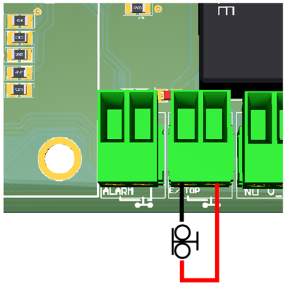
Pin 10, port 1 is used for E-Stop. Since this board controls the enable line, and the enable line is the one responsible for notifying the controller of the e-stop condition, the user does not have direct access to the pin itself, just to the e-stop terminal on the board. The E-Stop terminal is tied to the enable line and will trigger the E-Stop. A fault or E-Stop triggers a low for 5 seconds to notify the controller of the fault condition, then resets to high again.
10. 0 ALARM TERMINAL
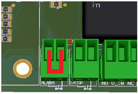
- If the terminal is not in use, it must have a jumper.
11.0 TYPICAL CONNECTIONS
- Connection with the terminal of the output source of 24VDC
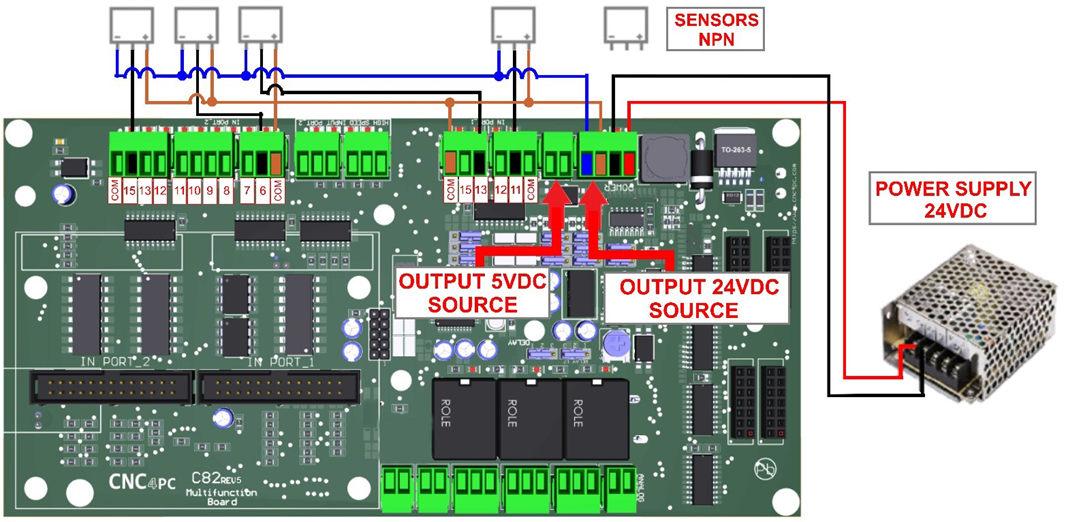
- Connection with the terminal of the output source of 5VDC
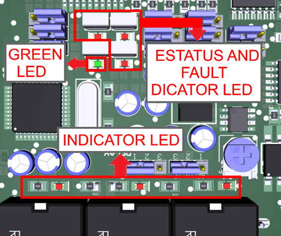
12.0 LED INDICATOR
The standby LED lights indicate that the system is ready but disabled. When the Status LED (Green LED) lights, it indicates that the system is enabled.
There are 4 possible error sources: a driver fault, E-STOP error, SCHP error, or VFD alarm. An LED will light close to the source of the fault.
VFD Connection and configuration jumper
The VFD Alarm monitoring feature can be enabled or disabled:
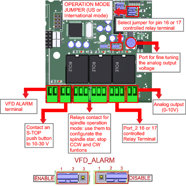
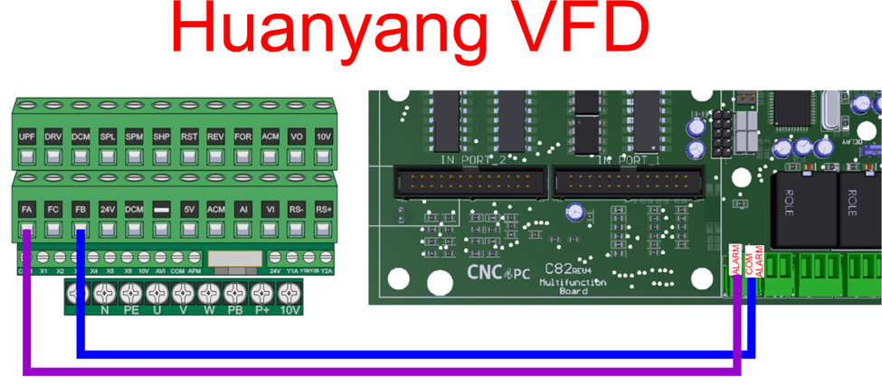
- The VFD Alarm will trigger when the contacts are open and the VFD Alarm is enabled.
- This VFD alarm input requires 5-24 VDC.
- For the Variable speed control, go to
instructions_variable_speed_control.pdf - To configure the control
software, go to
Configuration_of_Control_Sofware.pdf - To replace the Potentiometer, go to
Replacing_a_Potentiometer.pdf - ESS MOTHER BOARD
https://www.cnc4pc.com/ethernet-smooth-stepper-board.html
13.0 SAMPLE ENCODER WIRING
14.0 WIRING SAMPLE WITH C48.
15.0 DIMENSIONS
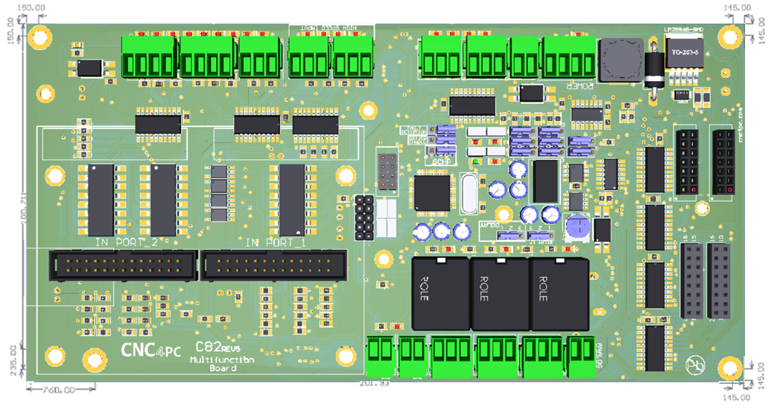
All dimensions are in Millimeters.
Fixing holes (4mm).