
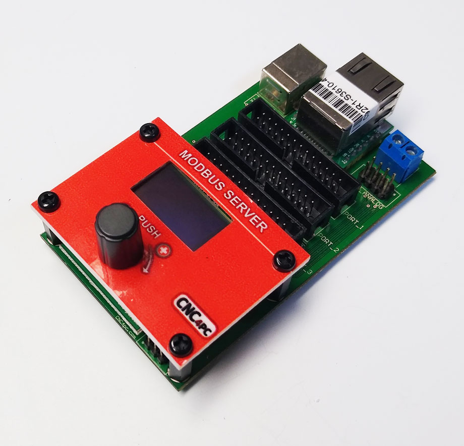
C92 – MODBUS SERVER
MAY 2024
1.0 OVERVIEW
This card provides you with a serious Modbus or TCP / IP connection and has 3 configurable ports for TTL outputs and an analog port
2.0 FEATURES
- ·MODBUS TCP/IP and USB protocol.
- Pins 2-9 on IDC26 can be bi-directional, determined by the internal configuration.
- Presentation Screen LCD
- It can be powered with a voltage of +5V, via the IDC26 pin, or from the USB connector.
- Compatible with the CNC controller board.
- 3 Expansion Ports. It has 3 x IDC26 connectors for additional Breakout or Relay Boards.
- IDC 8-pin male for analog input
- Visualization of the state of the pins on the display with TCP / IP
- IP configurable
- A display and an encoder for configuration
- Din rail mountable.
3.0 DESCRIPTION
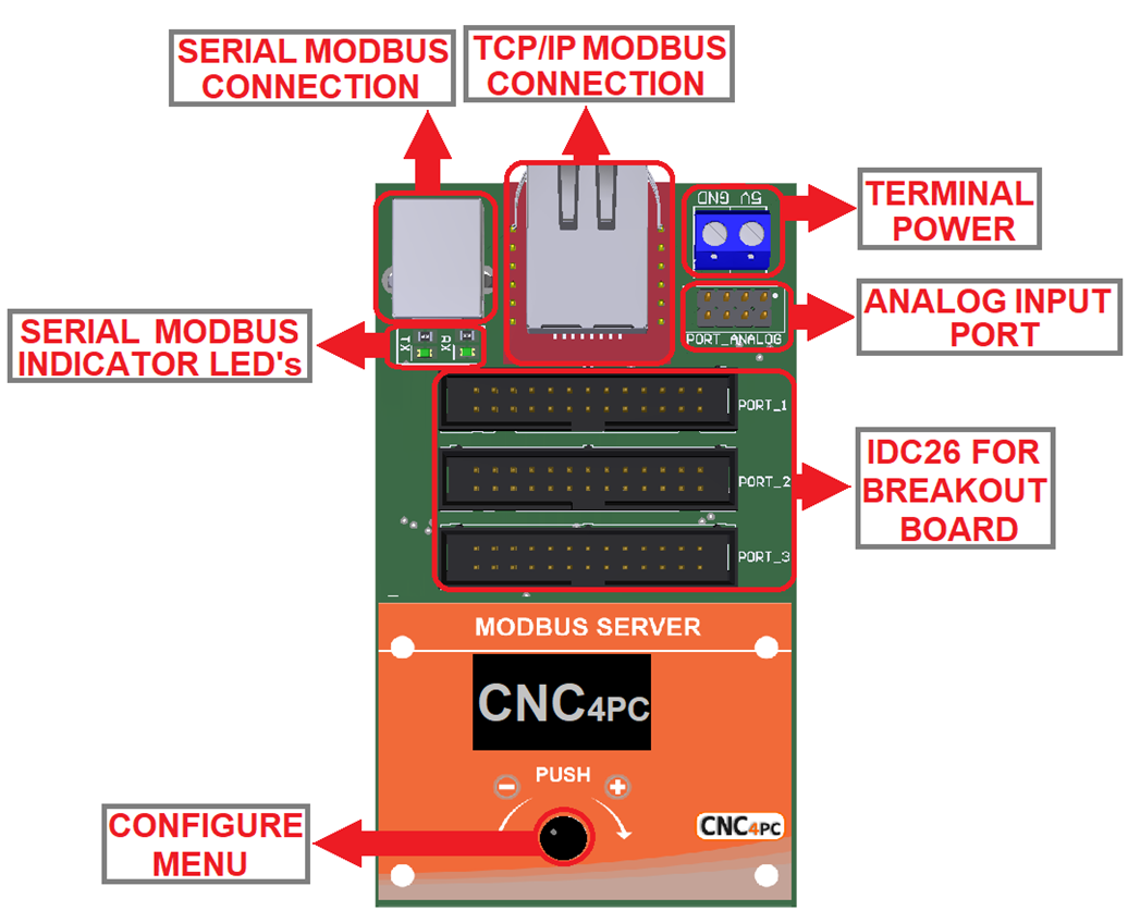
4.0 TERMINAL POWER
Regulated 5VDC @0.5A is required to power this board

5.0 MODBUS COMMUNICATION PROTOCOL
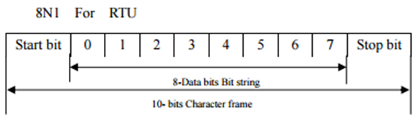
5.1 USB Communications
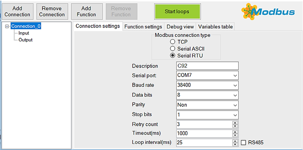
For Modbus RTU (Remote Terminal Unit) mode communications, the default parameters are the following:
Baud Rate = 38,400bps
Data Bits = 8
Parity = None
Stop Bits = 1
Flow Control = None
5.2 Configuring the control software
To configure, use the following sample configuration screen:
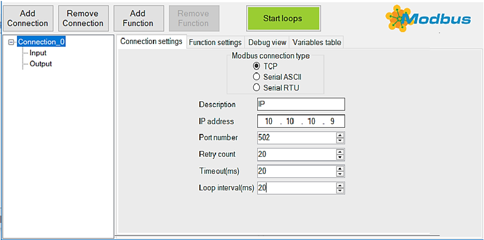
5.3 TCP/IP Communications
For Modbus TCP mode communications, the default parameters are the following:
IP address = Configurable in Board C92
Port number = 502
5.4 Configuring the control software
To configure, use the following sample configuration screen:
5.5 Board Modbus addresses
Analog, Input and output pin discrete.
|
FUNCTION NAME |
FUNCTION TYPE |
|
DISCRETE OUTPUT |
Write SingleCoils |
|
ANALOG INPUT |
Read InputRegisters |
|
DISCRETE INPUT |
Read Inputs |
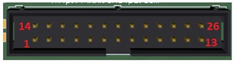
6.0 PINOUT
6.1 PORT_1
|
IDC26 PIN |
ADDRESS MODBUS
|
|
1 |
100 OUT |
|
2 |
104 IN/OUT |
|
3 |
105 IN/OUT |
|
4 |
106 IN/OUT |
|
5 |
107 IN/OUT |
|
6 |
108 IN/OUT |
|
7 |
109 IN/OUT |
|
8 |
110 IN/OUT |
|
9 |
111 IN/OUT |
|
10 |
112 IN |
|
11 |
113 IN |
|
12 |
114 IN |
|
13 |
115 IN |
|
14 |
101 OUT |
|
15 |
116 IN |
|
16 |
102 OUT |
|
17 |
103 OUT |
|
18 - 25 |
GND |
|
26 |
+5VDC |
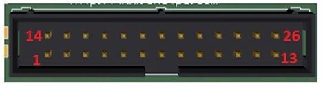
6.2 PORT_2
|
IDC26 Pin number |
ADDRESS MODBUS
|
|
1 |
200 OUT |
|
2 |
204 IN/OUT |
|
3 |
205 IN/OUT |
|
4 |
206 IN/OUT |
|
5 |
207 IN/OUT |
|
6 |
208 IN/OUT |
|
7 |
209 IN/OUT |
|
8 |
210 IN/OUT |
|
9 |
211 IN/OUT |
|
10 |
212 IN |
|
11 |
213 IN |
|
12 |
214 IN |
|
13 |
215 IN |
|
14 |
201 OUT |
|
15 |
216 IN |
|
16 |
202 OUT |
|
17 |
203 OUT |
|
18 - 25 |
GND |
|
26 |
+5VDC |
6.3 PORT_3
|
IDC26 PIN |
ADDRESS MODBUS
|
|
1 |
300 OUT |
|
2 |
304 IN/OUT |
|
3 |
305 IN/OUT |
|
4 |
306 IN/OUT |
|
5 |
307 IN/OUT |
|
6 |
308 IN/OUT |
|
7 |
309 IN/OUT |
|
8 |
310 IN/OUT |
|
9 |
311 IN/OUT |
|
10 |
312 IN |
|
11 |
313 IN |
|
12 |
314 IN |
|
13 |
315 IN |
|
14 |
301 OUT |
|
15 |
316 IN |
|
16 |
302 OUT |
|
17 |
303 OUT |
|
18 - 25 |
GND |
|
26 |
+5VDC |
6.4 PORT ANALOG INPUT
0-5vdc analog signals with 10bit ADC.

|
IDC8 PIN |
ADDRESS MODBUS
|
|
1 |
400 |
|
2 |
401 |
|
3 |
402 |
|
4 |
403 |
|
5 |
404 |
|
6 |
405 |
|
7 |
406 |
|
8 |
407 |
7.0 CONFIGURE MENU
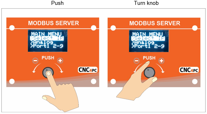
Press the knob for 2 seconds to enter setup mode.
Navigate through the setup menu by turning the knob.
Press the knob to change settings.
Turn the knob to adjust the value.
8.0 DIMENSION
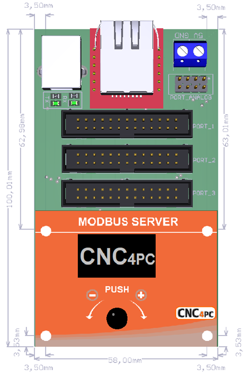
All dimensions are in millimeters
Fixing a hole (3mm).