
C25XP – MULTIFUNCTION CNC BOARD Rev.5
JULY 2025
1.0 FEATURES
- Can ship with the Ethernet Smooth Stepper Motion Controller installed when purchased as a bundle.
- Built-in PWM-Based Speed Control and Two Built-in Electromechanical Relays with NO and NC positions for spindle control.
- The system monitors:
- E-Stop.
- Safety Charge Pump.
- Driver Error. - Electromechanical Relay with NO and NC positions for general purpose (Port_2 16 or 17, jumper-selectable).
- Microcontroller-based SCHP (Safety Charge Pump).
- opt isolated inputs working at 5-24VDC.
- Uses a single +24VDC to power the system. It generates the isolated voltage for the spindle control circuit and +5VDC for circuits using TTL logic.
- Status LEDs on all input and Output connections.
- DIN Rail mountable.
- Open-Collector Outputs: pins 1, 14, 16, and 17 on Port 2.
- Screw-On connections for all terminals.
- Status LEDs for enable.
- The ENABLE Output of the C25XP is tied to LPT3. So that relay or breakout boards connected to LPT3 will be enabled/disabled with the C25XP.
- Available installers and configuration files that configure all the functions of the board.
- Driver Fault Detection pin. *NEW
- 4 pins can be used for High-Speed input. *NEW
2.0 I/O SPECIFICATIONS
|
PINS |
PORT1 |
PORT2 |
PORT3 |
TOTAL |
|
INPUT |
5 |
13 |
5 / 13 |
31 |
|
OUTPUT |
12 |
4 |
12 / 4 |
20 |
|
TOTAL |
17 |
17 |
17 |
51 |
OPTOISOLATED DIGITAL INPUT TTL SPECIFICATIONS
|
On-state voltage range |
5 to 24VDC |
|
Maximum off-state voltage |
0.8V |
|
Typical signal delay |
2.8uS |
DIGITAL OUTPUT TTL SPECIFICATIONS
|
Maximum output voltage |
5VDC |
|
Maximum output current |
24mA |
|
Maximum off-state voltage |
0.44 V |
|
Maximum supported frequency |
400KHz |
|
Typical signal delay |
10µS |
|
Time of transition to high impedance state |
12µS |
HIGH SPEED ENCODER INPUT
|
On-state voltage |
5 VDC |
|
Maximum off-state voltage |
0.8V |
|
Typical signal delay |
2.8uS |
|
Rise / Fall Time (Typ) |
50ns - 12ns |
OPEN COLLECTOR OUTPUT SPECIFICATIONS
|
Maximum output voltage |
60VDC |
|
Maximum output current |
2A |
|
Typical signal delay |
0.5 µS |
Relay 1 and 2
They can be used to control the VFD. The relay specifications are shown in this table.
ELECTROMECHANICAL RELAYS SPECIFICATIONS
|
Maximum Current (AC) |
2A@125VAC |
|
Maximum Current (DC) |
2A@60VDC |
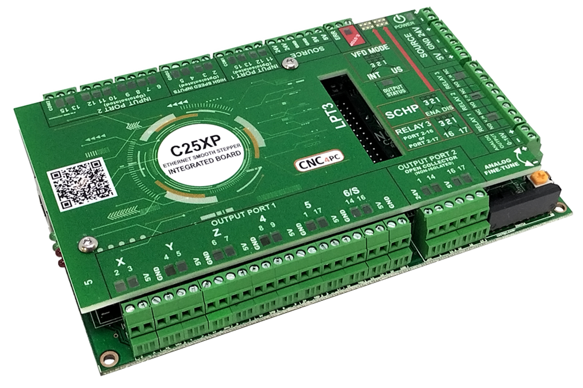
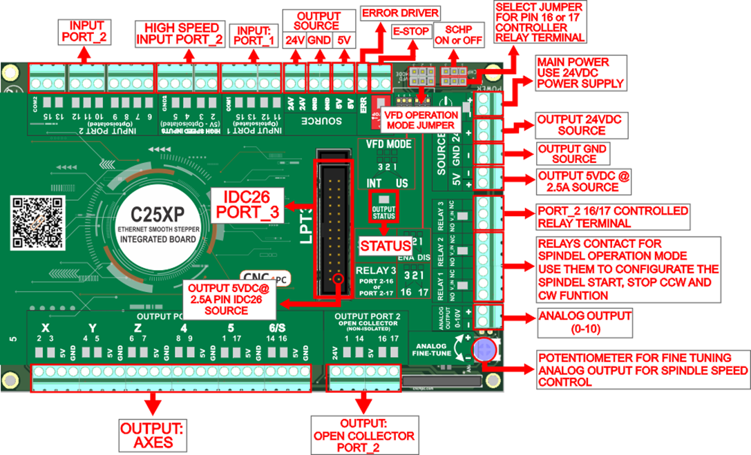
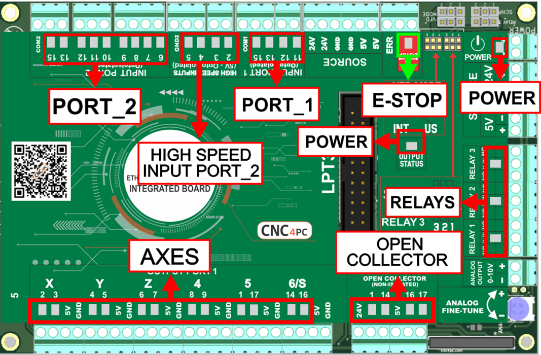
3.0 BOARD DESCRIPTION
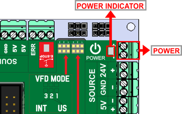
4.0 POWER TERMINALS AND CONFIGURATION
4.1 Power terminal
The board can typically be powered with regulated +24vdc, but it can also work with anything between +10VDC and +30VDC. The board itself will draw about 1 Amp, but we recommend using a 2A and up so it can power external devices.
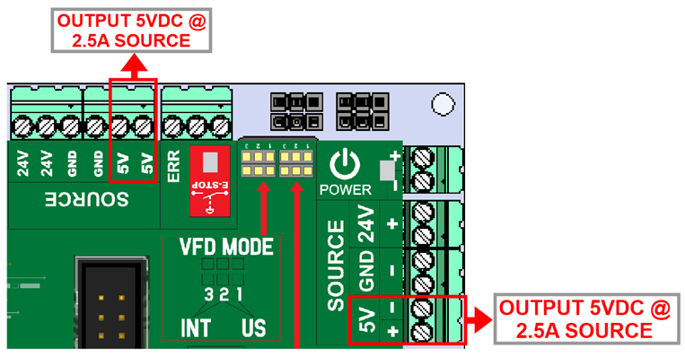
4.2 Source Output 5VDC
A regulated +5V DC supply of up to 2.5A can be used to power +5V DC external devices.
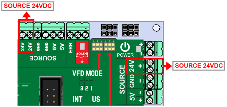
4.3 Source Output 24VDC
The same voltage that is used to power the board can be used to power external devices.
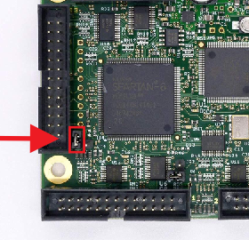
5.0 PORT_3 ESS
|
Pin |
Function |
|
P_1 |
OUTPUT |
|
P_2 |
IN/OUT |
|
P_3 |
IN/OUT |
|
P_4 |
IN/OUT |
|
P_5 |
IN/OUT |
|
P_6 |
IN/OUT |
|
P_7 |
IN/OUT |
|
P_8 |
IN/OUT |
|
P_9 |
IN/OUT |
|
P_10 |
INPUT |
|
P_11 |
INPUT |
|
P_12 |
INPUT |
|
P_13 |
INPUT |
|
P_14 |
OUTPUT |
|
P_15 |
INPUT |
|
P_16 |
OUTPUT |
|
P_17 |
OUTPUT |
|
P_18/25 |
GND |
|
P_26 |
5V |
The ENABLE Output of the C25XP is now tied to LPT3. So that relay or breakout boards connected to LPT3 will be enabled/disabled with the C25XP. Pin 26 also provides +5VDC to an external Relay or breakout board, making it easy and clean to integrate with other products.
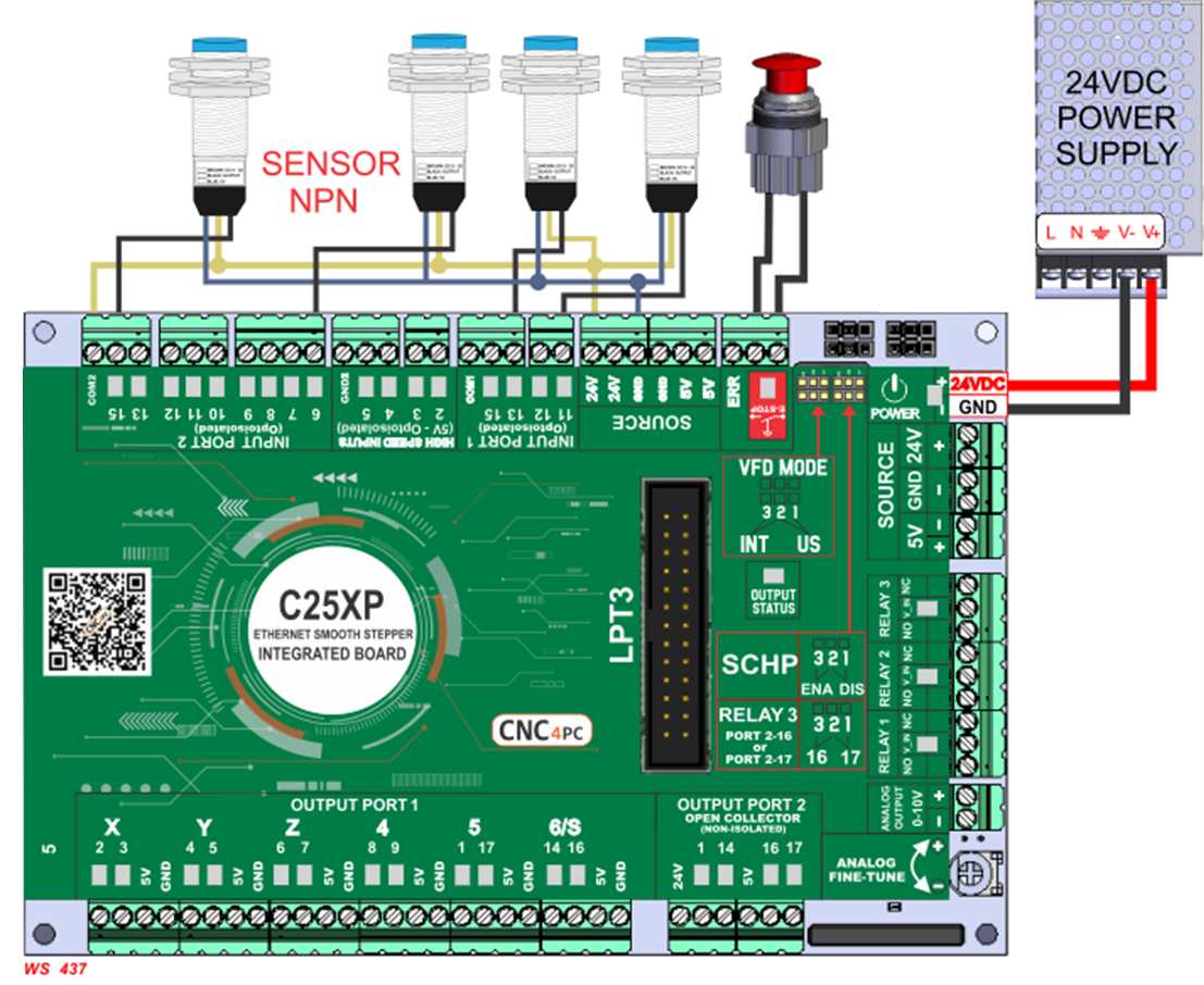
6.0 E-STOP TERMINAL (24V)
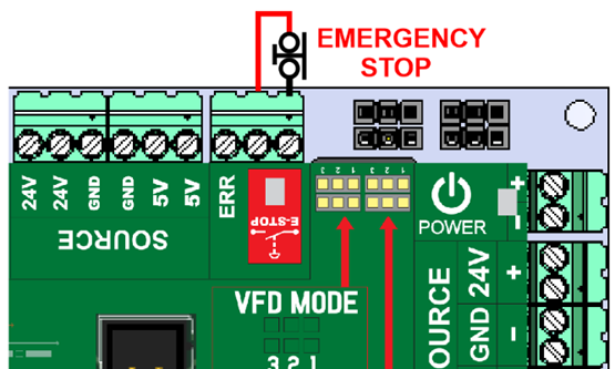
Connect an E-STOP push button as is shown in the images below.
Pin 10, port 1 is used for E-Stop. Since this board controls the enable line, which is responsible for notifying the controller of the e-stop condition, the user does not have direct access to the pin itself, but only to the e-stop terminal on the board. The E-Stop terminal is tied to the enable line and will trigger the E-Stop. A fault or E-Stop triggers a low for 5 seconds to notify the controller of the fault condition, then resets to high again
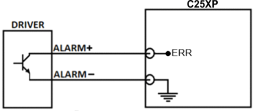
7.0 DRIVER ERROR
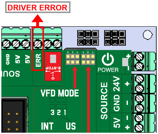
In order to start the driver monitoring function, it is necessary to connect the driver Alarm to the ERR terminal.
7.1 WIRING DRIVER ERROR
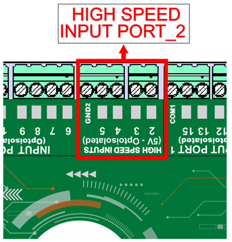
8.0 HIGH SPEED INPUTS
PORT_2 PIN 2, 3, 4, AND 5. These terminals support signals 5VDC.
9.0 CONFIGURATION JUMPERS
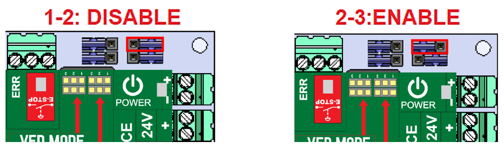
9.1 Selecting the SCHP operation mode
The Safety Charge Pump uses pin 17 on port 2. When the SCHP is enabled on the board, then the output of the terminals will be active while the Safety Charge Pump signal is present and inactive while the SCHP is not present.
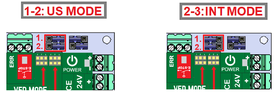
9.2 Configuration jumper mode US or INT
Set jumpers 1 and 2 in the corresponding positions for the desired configuration mode.
- For the Variable speed control, go to
instructions_variable_speed_control.pdf - To configure the control
software, go to
Configuration_of_Control_Sofware.pdf - To replace the Potentiometer, go to
Replacing_a_Potentiometer.pdf - ESS MOTHER BOARD
https://www.cnc4pc.com/ethernet-smooth-stepper-board.html
9.3 Configuration jumper pin 16 or 17
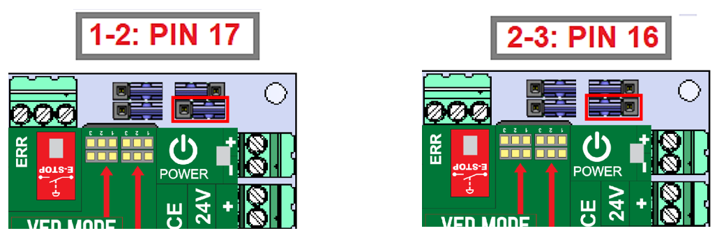
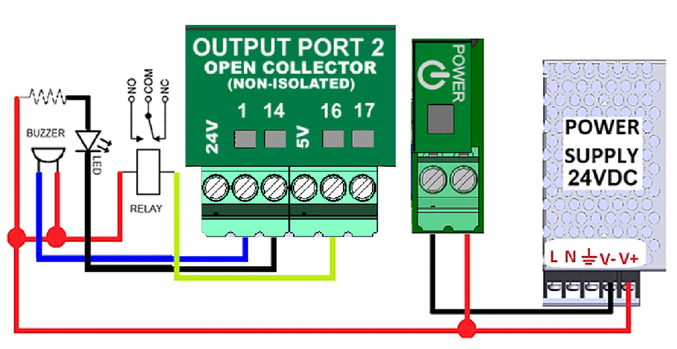
10.0 GENERAL PURPOSE OUTPUT TERMINALS
Open Collector Outputs Sample Wiring
11.0 LEDs
12.0 WIRING SAMPLE INPUT PORT_1 AND PORT_2
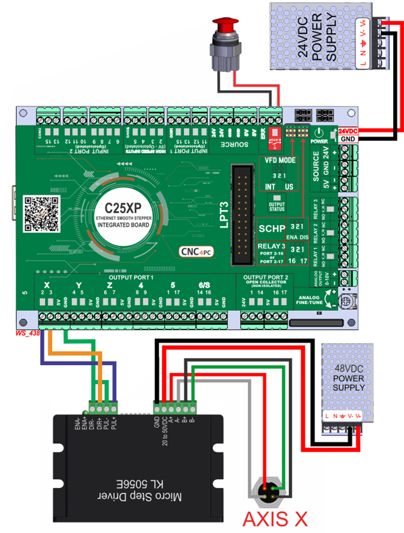
13.0 AXIS WIRING SAMPLE
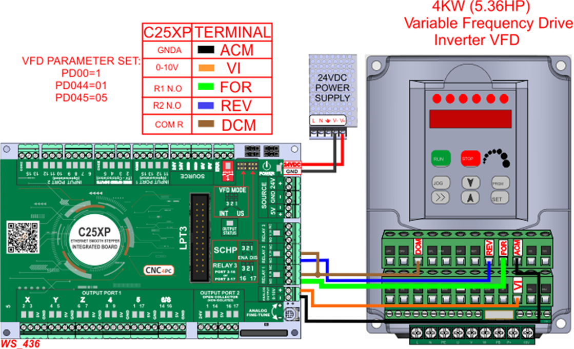
14.0 WIRING SAMPLE VFD
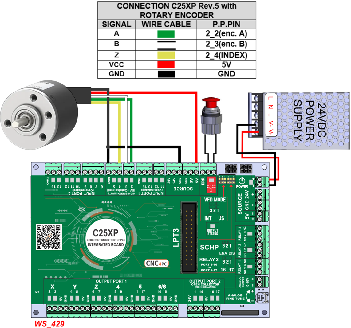
15.0 WIRING SAMPLE ENCODER
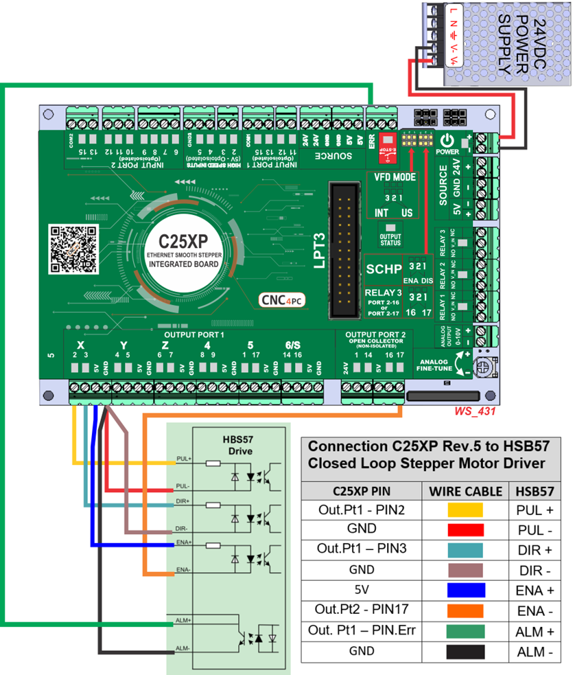
16.0 WIRING SAMPLE DRIVE FAULT DETECTION
17.0 DIMENSIONS
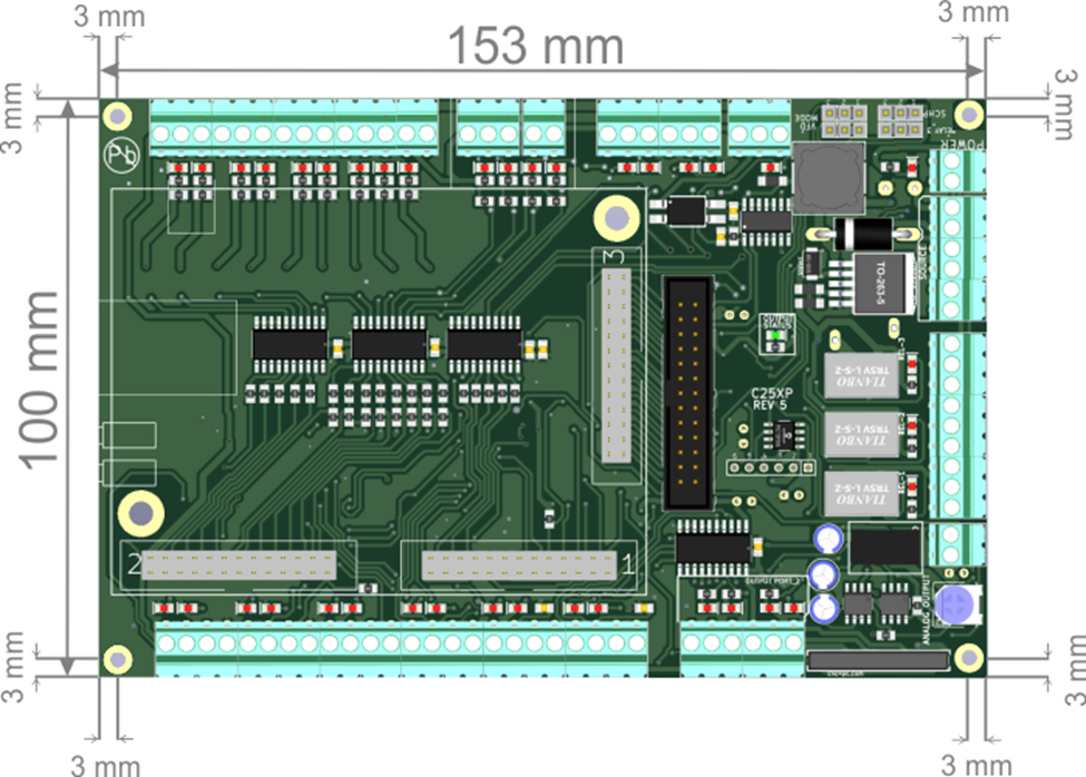
All dimensions are in Millimeters.