
C80- EXPANSION BOARD Rev. 2
MAY, 2025
TABLE OF CONTENTS
1.0 OVERVIEW
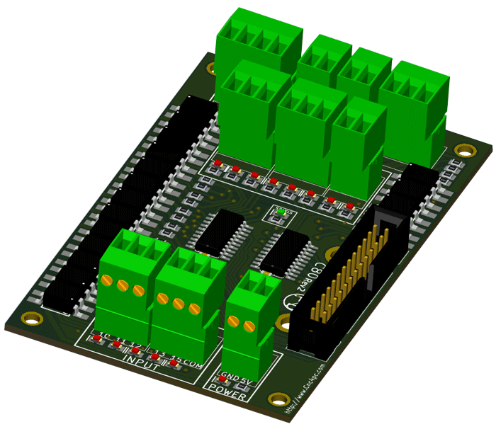
This card provides an easy way to connect your inputs and outputs from your port using an LPH26-pin ribbon Cable or a parallel port. It provides terminals for connections and condition signals for use in CNC applications. This version can be easily mounted on control boxes using DIN rails and accommodate ribbon cables or DB25 connectors.
2.0 FEATURES
- Terminal Block for all I/Os.
- Expansion port for the Board. Connect the C76 or ESS expansion board.
- Open collector Outputs pins optoisolated 2, 3, 4, 5, 6, 7, 8, 9, 1, 14, 16, 17.
- Input pins 10, 11, 12, 13, 15.
- Terminal Block input with close-by ground or +5VDC connections, COM, and outputs with + 24VDC and ground
- Status LEDs for enabling.
- Fully Optoisolated Inputs and Outputs.
- External Enable Pin.
- Din rail mountable.
- Pluggable Screw-On Terminals.
3.0 SPECIFICATIONS
|
DIGITAL INPUT SPECIFICATIONS |
|
|
Maximum off-state voltage |
0.8V |
|
Maximum operation frequency |
4 MHz |
|
Typical signal delay |
10nS |
|
DIGITAL OUTPUT OPEN COLLECTOR SPECIFICATIONS |
|
|
Maximum output voltage |
(24V power supply voltage) |
|
Typical output current |
6A |
|
Maximum operation frequency |
4 MHz |
|
Typical signal delay |
0.25 µS |
|
Time of transition to high impedance state |
12 s* |
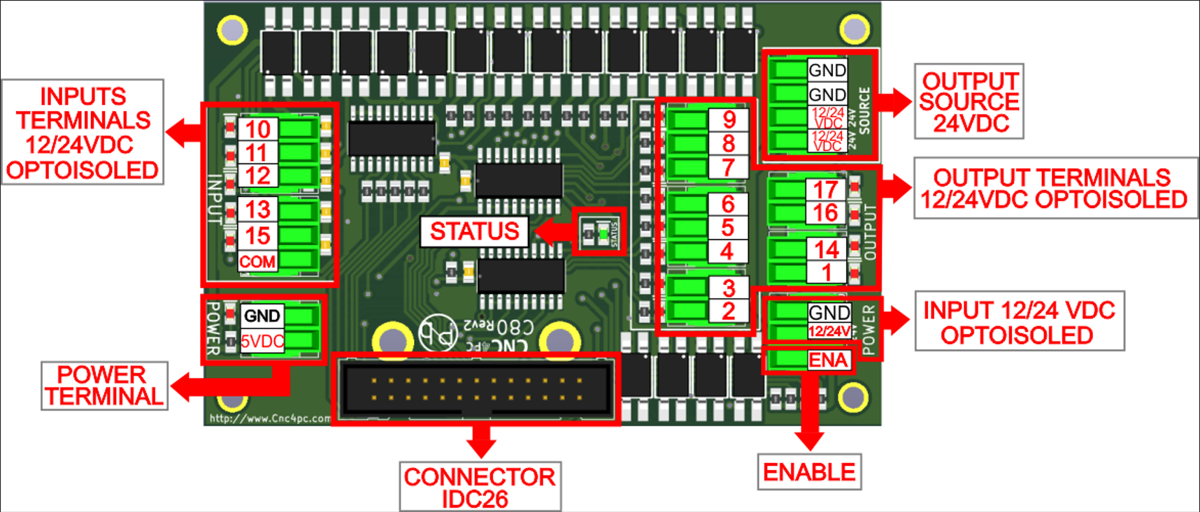
4.0 BOARD DESCRIPTION
5.0 REQUIREMENTS
5.1 Power Requirements
Regulated +5VDC and + 24VDC are required to power this board.
6.0 POWER TERMINAL
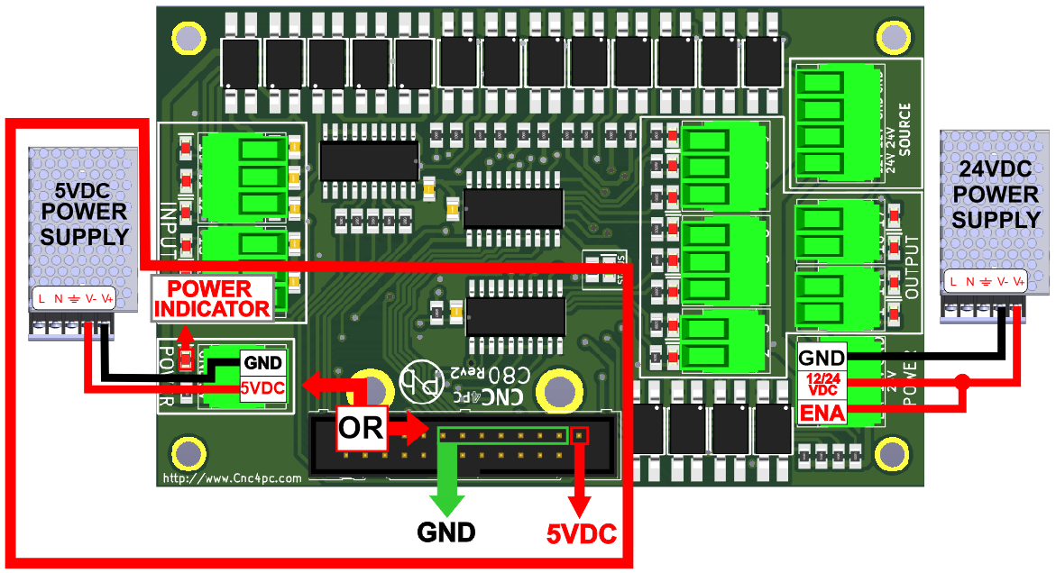
To preserve optoisolation, two independent power sources should be used: a +5VDC to power the optos that interact with the controller (a USB cable) and a +24VDC at 200mA to power the board.
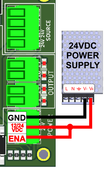
6.1 Enable pin.
The card must be provided with a 24VDC signal to enable operation. This feature has been added to externally control the status of the outputs. An external switch or a Safety Charge Pump can be added to provide the enabling signal. If this function is not required, a jumper can be placed between 24VDC and the EN terminal.
7.0 LED INDICATOR
The power LED lights indicate that the system is ready but disabled. When the Status LED (Green LED) lights, it indicates that the system is enabled.
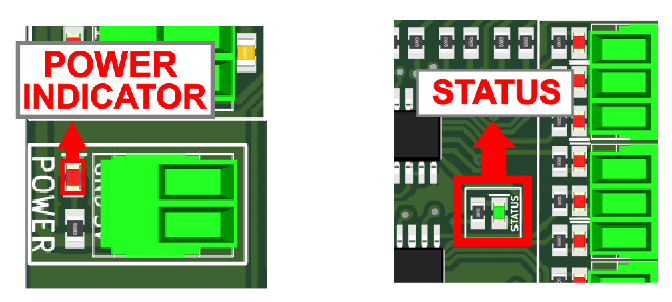
3 conditions need to be met to get the STATUS LED to light:
- The board needs to be powered.
- The Enable terminal requires +24V DC from the jumper. The board ships with a jumper cable.
- The IDC26 connector must be connected to provide a ground signal from pin 18 to pin 19. This validates that the board is connected to a controller.
8.0 PINOUT
8.1 Pin Numbering
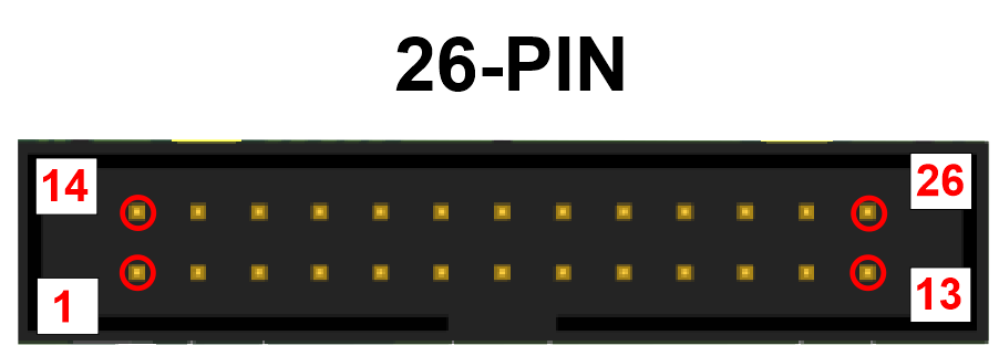
8.2 IDC26
| IDC26 PIN | LPT port direction signal |
| 1 | Output 1 |
| 2 | Output 2 |
| 3 | Output 3 |
| 4 | Output 4 |
| 5 | Output 5 |
| 6 | Output 6 |
| 7 | Output 7 |
| 8 | Output 8 |
| 9 | Output 9 |
| 10 | Input 10 |
| 11 | Input 11 |
| 12 | Input 12 |
| 13 | Input 13 |
| 14 | Output 14 |
| 15 | Input 15 |
| 16 | Output 16 |
| 17 | Output 17 |
| 18 | Watchdog (Ground to Enable) |
| 19 - 25 | GND |
| 26 | +5VDC |
COMPATIBILITY Regular Parallel Port, ESS, 5LPT, C76, UC100
9.0 CONFIGURATION SWITCHES
9.1 Connecting Switches Using the COM = 12/24VDC
There is a jumper that allows you to select +12/24VDC or GND for the COM pins.
While this board supports input +24VDC signals, different kinds of sensors and switches using different voltages can be connected using the diagrams that follow:
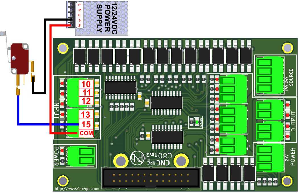
Fig. 1 Wiring diagram to connect switches.
9.2 Connecting Switches Using the COM = GND
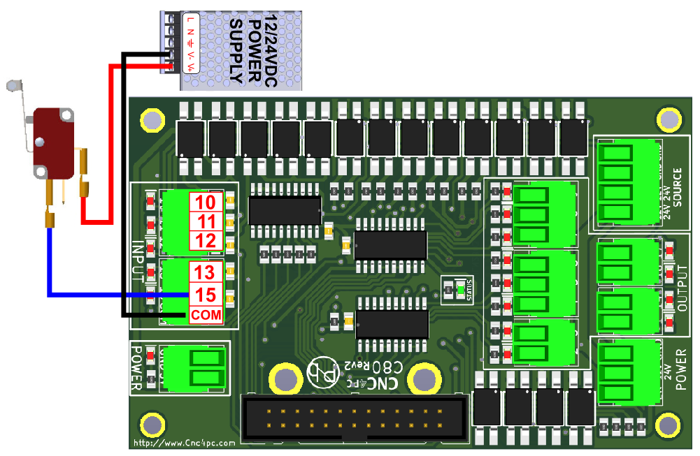
Fig. 2 Wiring diagram to connect switches.
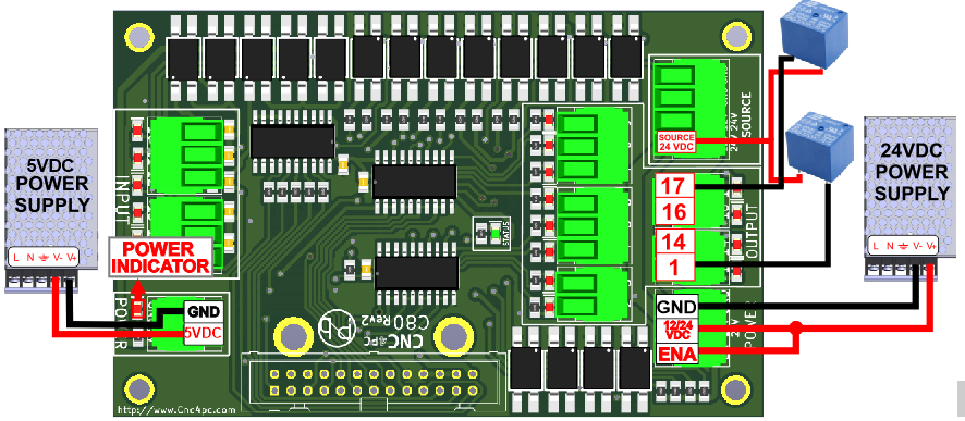
10.0 EXAMPLE WIRING OPTOISOLATED OUTPUT
The power source of 12/24 VDC is for the correct functioning of the outputs of (2-9) and (1,14,16,17).
11.0 WIRING DIAGRAM SENSORS
11.1 Connecting PNP sensors.
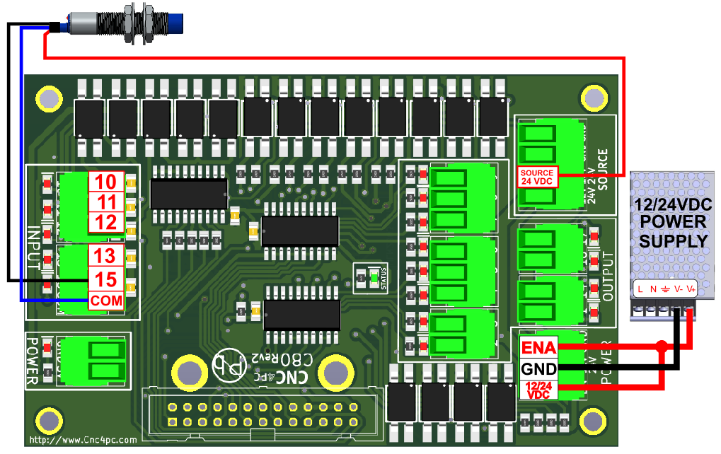
Fig. 3 Wiring diagram to connect PNP open collector proximity sensors.
11.2 Connecting NPN sensors.
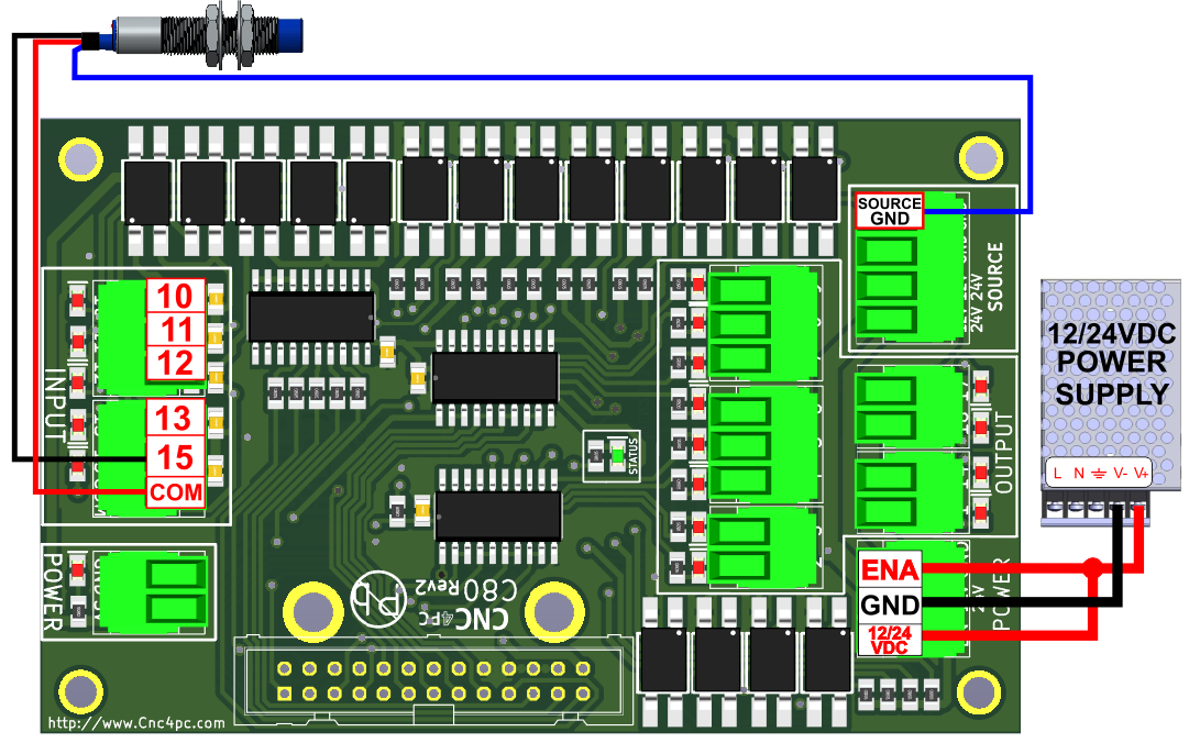
Fig. 4 Wiring diagram to connect in parallel NPN open collector proximity sensors.
12.0 DIMENSIONS
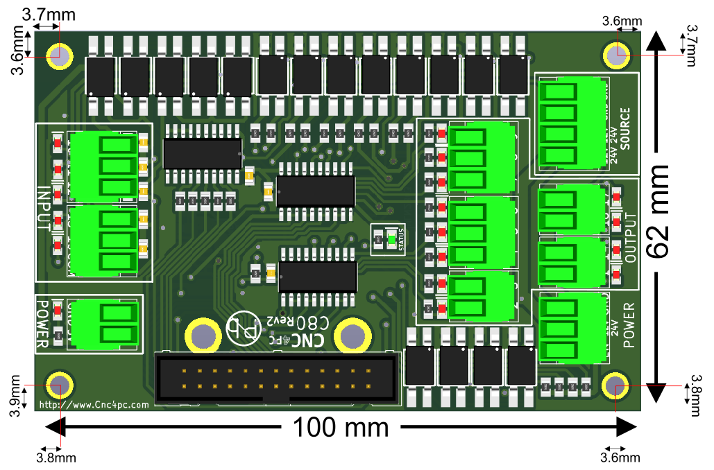
All dimensions are in Millimeters.
Fixing holes (4mm).