Skip to Content

Welcome!

Share and discuss the best CNC projects

Sign up

You need to be registered to interact with the community.
This question has been flagged
2 Replies
74 Views

OK. I think I've read and searched the manual and the website very thoroughly  and I can't find this info.

What ESS port/pins are the C25XP spindle connections connected to?

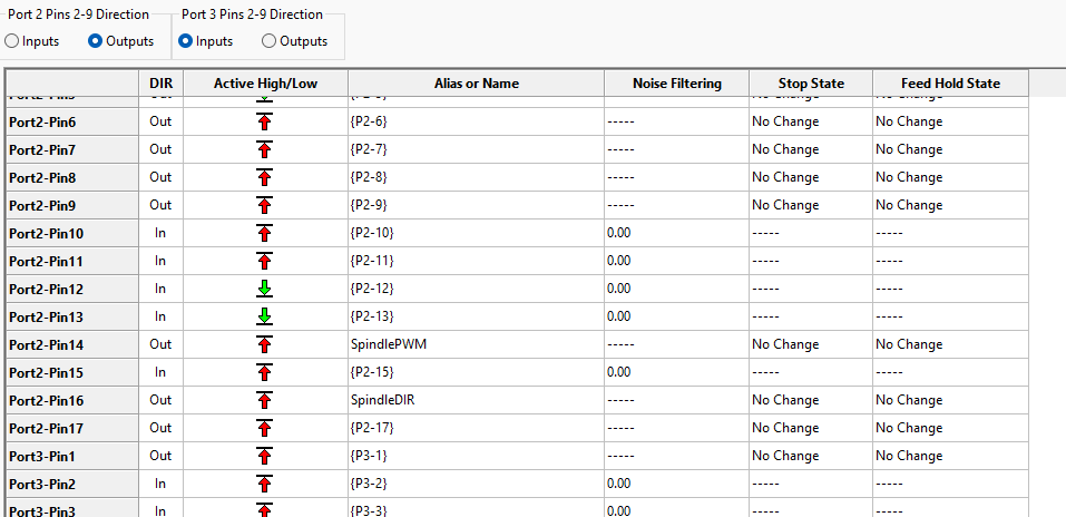
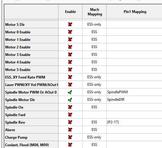
I have successfully got relay 3 working and found the instructions for assigning it pin 16 or pin 17, but I cannot find what port/pins the PWM port, and relay 1 and relay 2 are connected to with the C25XP.


I recently rewired my entire machine and decided to upgrade from the spider of wires connected to (3) old Probotix BOBs and I have everything working perfectly (except the spindle).  I've wired the spindle per the C25XP instructions so I feel like once I know the pins, config will be easy and quick, but it doesn't seem to be documented anywhere I can find.


Any help appreciated, thanks!!

james

Avatar
Discard
Author Best Answer

Thanks Arturo,


I had this working perfectly with the C41, but I also knew exactly what the pin mapping was for that from my old BOB.   I am still struggling with the C25XP.  I moved config to 2-14 PWM and 2-16 Direction (screenshots attached). I assume that the demo wiring in the manual is setup for the "US" jumper settings, but I did try both and neither work.  No matter what I do I can't get relay 1 or relay 2 to turn on.  I believe the PWM signal *IS* present so I think I am OK there, just can't get the direction relays to do anything.  What am I missing here?  Thanks again

James

Avatar
Discard

You have PWM and DIN on port 2, it is port 1. YES! It is the same configuration as the C41, but the C25XP is hardwired to pins 14 and 16 on PORT 1.

Best Answer

The C25XP handles the Spindle Relays.  It expects PWM at 300hz on Pin 14 on Port 1 and Direction on Port 16 on Port 1.

Presence of PWM = Spindle ON.

The jumpers on the board determine the relay logic:

US Mode:  Relay 1 = FOR and Relay 2 = REV.

INTernational = Relay 1 = On/Off and Relay 2 = CW/CCW.

Note that in the US, motors are controlled with a forward and reverse input, but in the rest of the world, they do an on/off and direction signal.  You can also find this setting on most VFDs.

Make sure not to assign other pins or signals to pins 14 and 16 on port 1, as it will create a pin conflict. 

The initial configuration that you did with the Step-by-Step instructions for the C25XP left your spindle configured, and you only need to set the max spindle speed.


Avatar
Discard