C94 – MULTIFUNCTION CNC BOARD Rev.2
OCTOBER 2022
USER'S MANUAL TABLE OF CONTENTS
1.0
FEATURES
- Can ship the UC300ETH Motion Controller installed when purchased as a bundle
- Emulates 5 Parallel Ports.
- 3 Expansion Ports for connecting additional breakout or relay boards.
- Two Analog Inputs and Two Outputs.
- Built-in PWM-Based Speed Control and Two Built-in Electromechanical Relays with NO and NC positions for spindle control.
- The system monitors:
- E-Stop
- Safety Charge Pump. - Electromechanical Relay with NO and NC positions for general purpose or tied to the Enable Signal (Port_2 16 or 17, jumper-selectable).
- Microcontroller-based Safety Charge Pump (SCHP).
- Optoisolated inputs working at 5-24VDC.
- Uses a single voltage of 10 to 30VDC to power the system. It generates the isolated voltage for the spindle control circuit and +5VDC for circuits using TTL logic.
- Status LEDs on all Input and Output connections.
- DIN Rail mountable.
- Open-Collector Outputs: pins 1, 14, 16, and 17 on port 2.
- Screw-On connections for all terminals.
- Status LEDs for enable.
- Available installers and configuration files that configure all the functions of the board.
2.0 I/O SPECIFICATIONS
Inputs and Outputs are jumper-selected to be TTL or Open collector.
|
PINS |
PORT1 |
PORT2 |
PORT3 |
PORT4 |
PORT5 |
TOTAL |
|
INPUT |
5 |
13 |
13 |
5 |
13 |
49 |
|
OUTPUT |
12 |
4 |
4 |
12 |
4 |
36 |
|
TOTAL |
17 |
17 |
17 |
17 |
17 |
93 |
OPTOISOLATED DIGITAL INPUT TTL SPECIFICATIONS
|
On-state voltage range |
5 to 24VDC |
|
Maximum off-state voltage |
0.8V |
|
Typical signal delay |
2.8uS |
DIGITAL OUTPUT TTL SPECIFICATIONS
|
Maximum output voltage |
5VDC |
|
Maximum output current |
50mA |
|
Maximum off-state voltage |
0.44 V |
|
Maximum supported frequency |
400KHz |
|
Typical signal delay |
10nS |
|
Time of transition to high impedance state |
12 s* |
OPEN COLLECTOR OUTPUT SPECIFICATIONS
|
Maximum output voltage |
60VDC |
|
Maximum output current |
2A |
|
Typical signal delay |
0.5 µS |
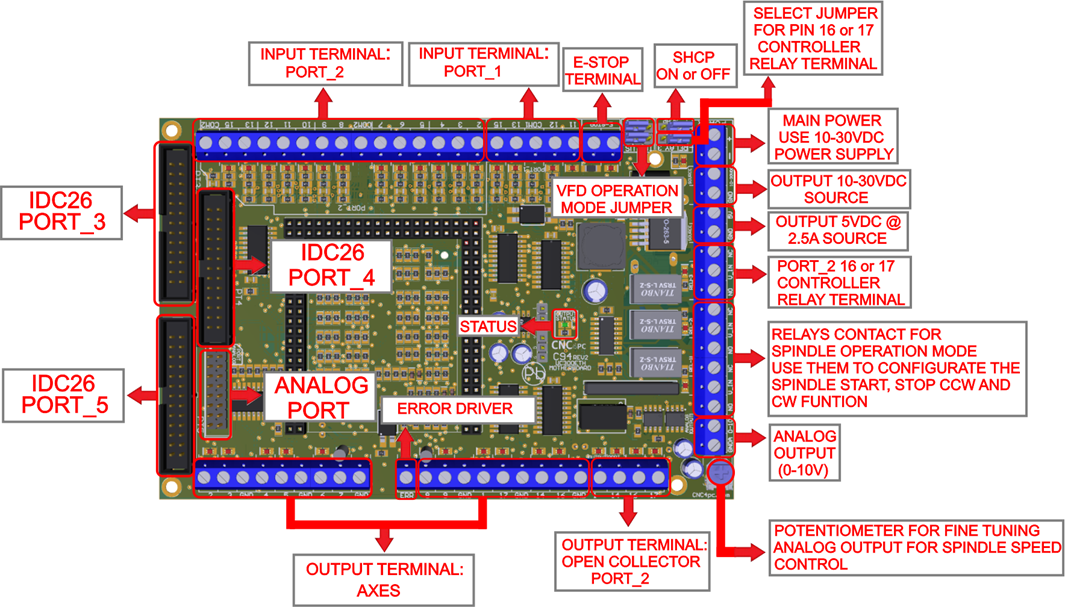
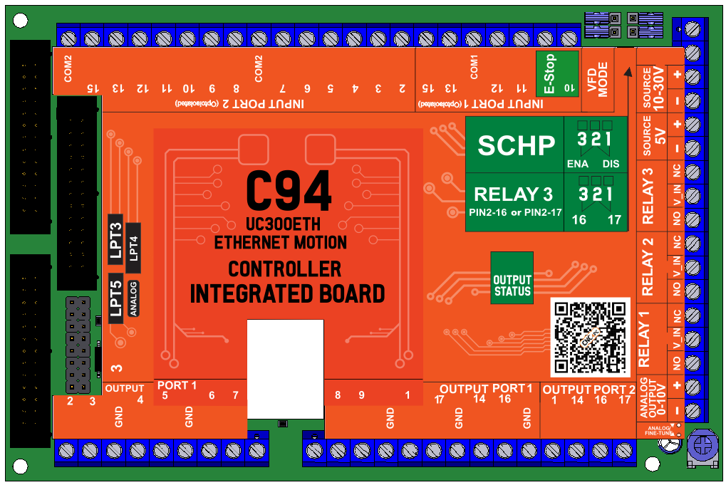
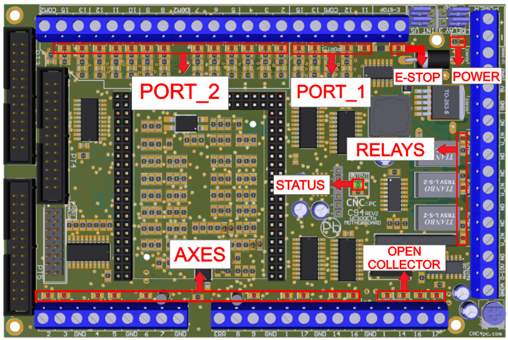
3.0 BOARD DESCRIPTION
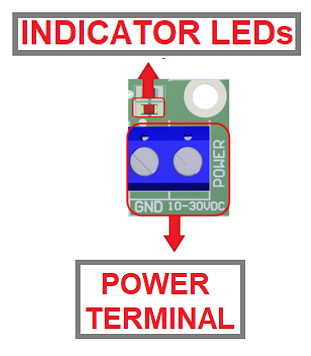
4.0 POWER TERMINALS AND CONFIGURATION
4.1 Power terminal
Regulated +10VDC or +30VDC at 2 Amps is required to power this board. Additional amperage must be supplied if sourcing current on the open collector outputs or using the Expansion IDC26 ports to power breakout or relay boards.
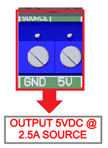
4.2 Source Output 5VDC
The board can supply a regulated voltage to power external devices or circuits.
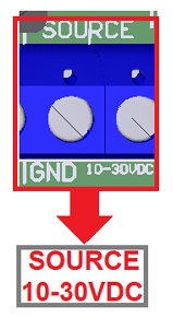
4.3 Source Output 10-30VDC
10-30VDC can be sourced to sensors or other cards requiring it.
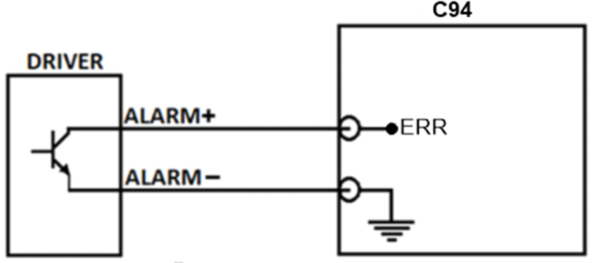
4.4 ERROR DRIVER
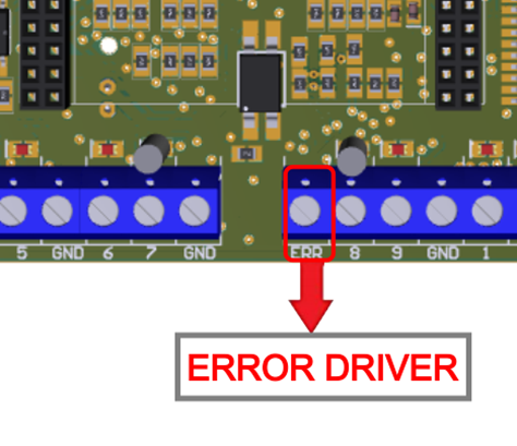
In order to start the driver monitoring function, it is necessary to connect the driver Alarm to the ERR terminal.
4.4 WIRING ERROR DRIVER
5.0 LPT_3 AND LPT_5 INPUT EXPANSION PORT
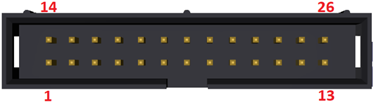
LPT 3 and LPT 5
|
Equivalent P.P. Pin |
UC300 Function |
|
P_1 |
OUTPUT |
|
P_2 |
INPUT |
|
P_3 |
INPUT |
|
P_4 |
INPUT |
|
P_5 |
INPUT |
|
P_6 |
INPUT |
|
P_7 |
INPUT |
|
P_8 |
INPUT |
|
P_9 |
INPUT |
|
P_10 |
INPUT |
|
P_11 |
INPUT |
|
P_12 |
INPUT |
|
P_13 |
INPUT |
|
P_14 |
OUTPUT |
|
P_15 |
INPUT |
|
P_16 |
OUTPUT |
|
P_17 |
OUTPUT |
|
P_18 |
GND |
6.0 LPT_4 OUTPUT EXPANSION PORT
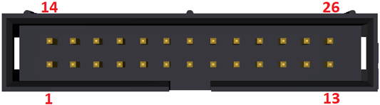
LPT 4
|
Equivalent P.P. Pin |
UC300 Function |
|
P4_1 |
OUTPUT |
|
P4_2 |
OUTPUT |
|
P4_3 |
OUTPUT |
|
P4_4 |
OUTPUT |
|
P4_5 |
OUTPUT |
|
P4_6 |
OUTPUT |
|
P4_7 |
OUTPUT |
|
P4_8 |
OUTPUT |
|
P4_9 |
OUTPUT |
|
P4_10 |
INPUT |
|
P4_11 |
INPUT |
|
P4_12 |
INPUT |
|
P4_13 |
INPUT |
|
P4_14 |
OUTPUT |
|
P4_15 |
INPUT |
|
P4_16 |
OUTPUT |
|
P4_17 |
OUTPUT |
|
P4_18 |
GND |
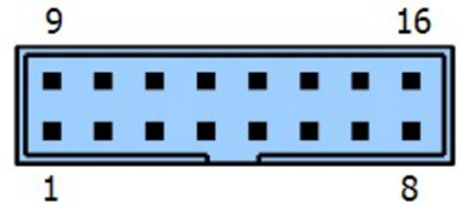
7.0 ANALOG I/O PORT PINOUT.
The analog port contains 2 analog inputs and 2 analog outputs. This port also contains a 5V power output.
|
Pin |
Signal direction |
|
1 |
5 Volt output |
|
2 |
Ground |
|
3 |
Analog input 1. |
|
4 |
Analog input 2. |
|
5 |
Ground |
|
6 |
Analog output 1. |
|
7 |
Analog output 2. |
|
8 |
5 Volt output |
|
9 |
5 Volt output |
|
10 |
Ground |
|
11 |
Analog input 1. |
|
12 |
Analog input 2. |
|
13 |
Ground |
|
14 |
Analog output 1. |
|
15 |
Analog output 2. |
|
16 |
5 Volt output |
8.0 E-STOP TERMINAL (24V)
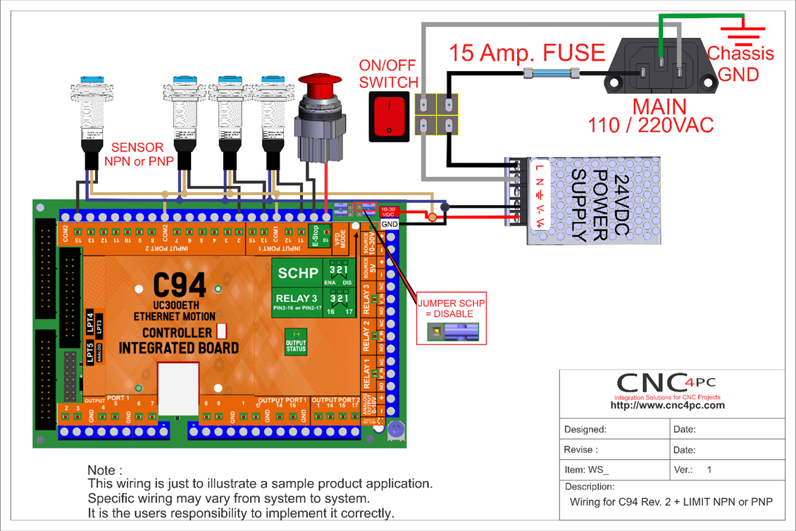
Connect an E-STOP push button as shown in the images below.
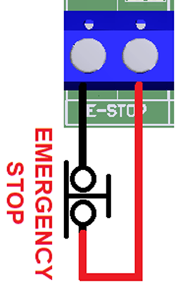
Pin 10, port 1 is used for E-Stop. Since this board controls the enable line, and the enable line is the one responsible for notifying the controller of the e-stop condition, the user does not have direct access to the pin itself, just to the e-stop terminal on the board. The E-Stop terminal is tied to the enable line and will trigger the E-Stop. A fault or E-Stop triggers a low for 5 seconds to notify the controller of the fault condition, then resets to high again
9.0 CONFIGURATION JUMPERS
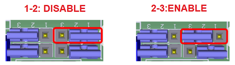
9.1 Selecting the SCHP operation mode
The Safety Charge Pump can be activated or deactivated depending on the jumper position. If the SCHP is enabled, the board will require the SCHP coming from the controller to be present in order to get activated (green LED).
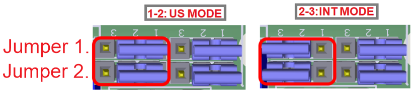
9.2 Configuration jumper mode US or INT
Relay 1 and 2
They can be used to control the VFD. The relay specifications are shown in this table.
ELECTROMECHANICAL RELAYS SPECIFICATIONS
|
Maximum Current (AC) |
2A@125VAC |
|
Maximum Current (DC) |
2A@60VDC |
- For the Variable speed control, go to
instructions_variable_speed_control.pdf - To configure the control
software, go to
Configuration_of_Control_Sofware.pdf - To replace the Potentiometer, go to
Replacing_a_Potentiometer.pdf
UC300ETH MOTHER BOARD
https://www.cnc4pc.com/uc300eth-ethernet-motion-controller-b.html
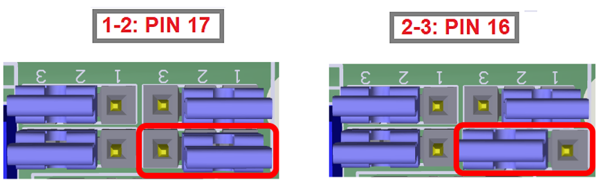
9.3 Relay 3 Operation can be assigned to pins 16 or 17 on port 2.
If assigning the relay to pin 17 on port 2 and using the Safety Charge Pump, then the relay will activate with the board is activated. This can be very useful as it can be used to activate the main contactor for the system or relays that activate devices.
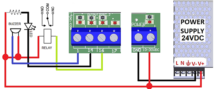
10.0 GENERAL PURPOSE OUTPUT TERMINALS
Open Collector Outputs Sample Wiring
11.0 LEDs
12.0 WIRING SAMPLE FOR INPUT PORT_1 AND PORT_2
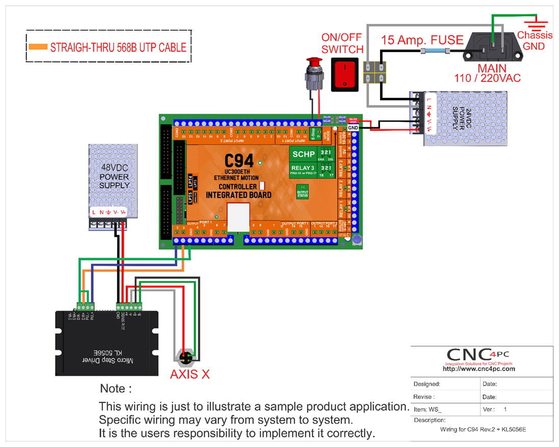
13.0 AXES WIRING SAMPLE
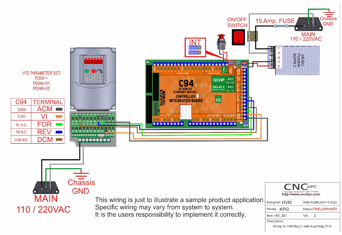
14.0 WIRING SAMPLE VFD
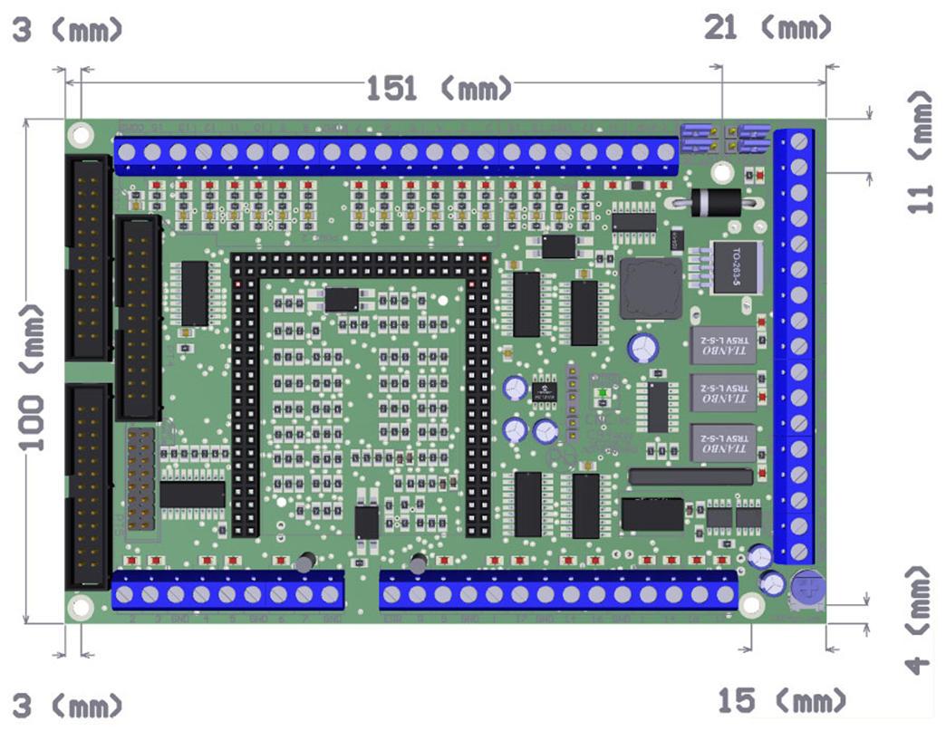
15.0 DIMENSIONS