The files on this version only work with Firmware FF5V11.
Used software: UCCNC Version 1.2115.
https://www.cncdrive.com/UCCNC/setup_1.2115.exe
Screen and Macros:
https://www.cnc4pc.com/pub/media/productattachments/files/UCCNC_THC-2.zip
THC-2 Rev 5.1 FIRMWARE: FF5V11
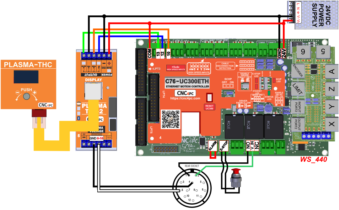
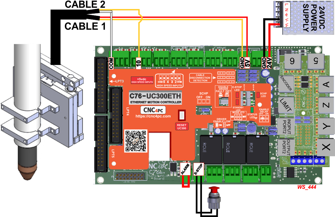
1.2. Wiring sample.
These wiring samples for connection can be used:
Connection C76 Rev.4 and THC-2 Rev.5 with Plasma Everlast 102i (cnc4pc.com)
Connection C76 Rev.4 and PTS-1.
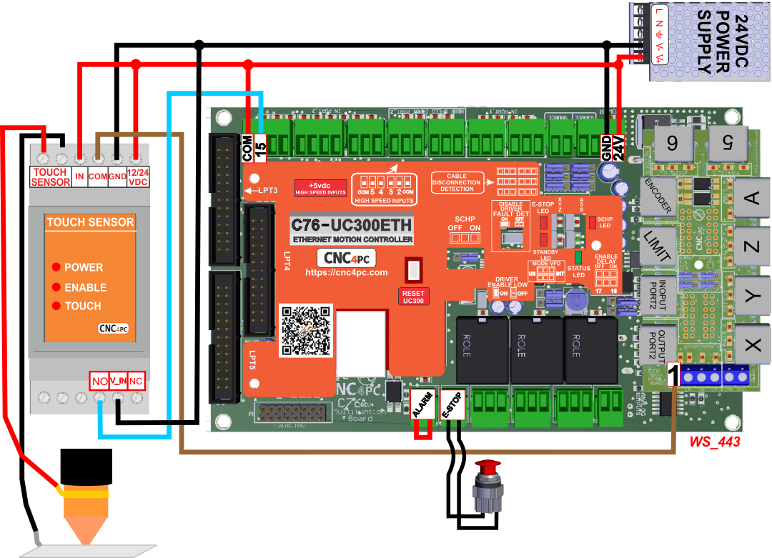
Connection C76 Rev.4 and Plasma Floating Head.
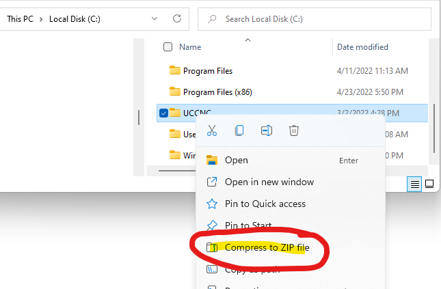
Start by making a backup of the existing installation:
Make a backup of the configuration and file installation, we recommend creating a backup of the current installation by right-clicking in the current installation folder and zipping it.
Before configuring the THC make sure you have wired and configured and tested the initial probing. This could be done with the Plasma Touch Sensor or a Floating Head.
Complete the configuration stages
1. Basic Installation.
You can choose between running an automatic installer that copies all the files and configures Mach4 or you can copy the files and make all the configuration changes manually
1.1. Automatic Installation.
Download, extract, and run the installation program as shown in the video
https://cnc4pc.com/mpattachments/file/viewonline/id/1825/product_id/2225/
1.2. Manual Installation.

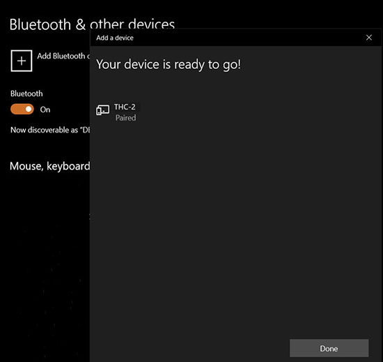
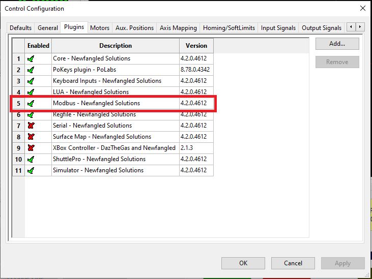
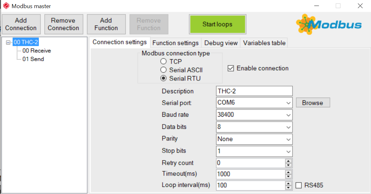
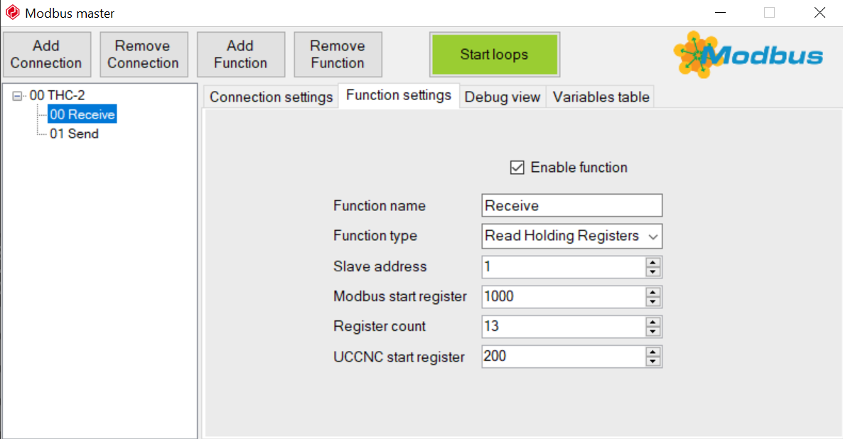
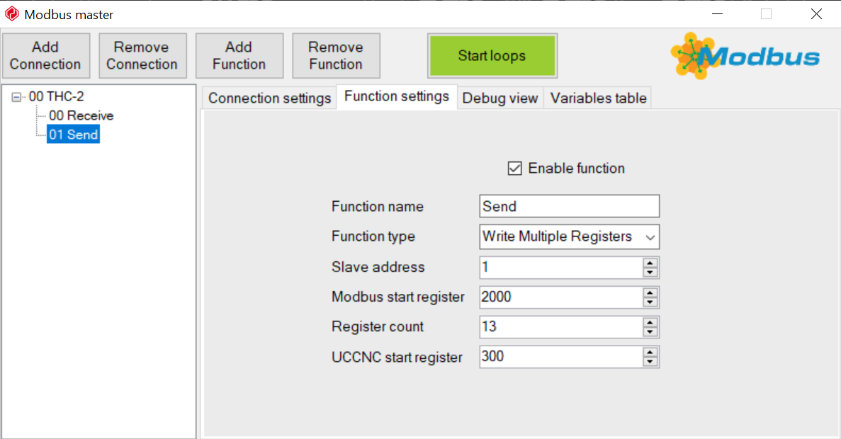
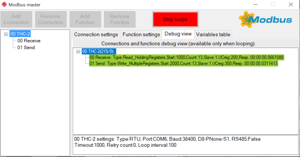
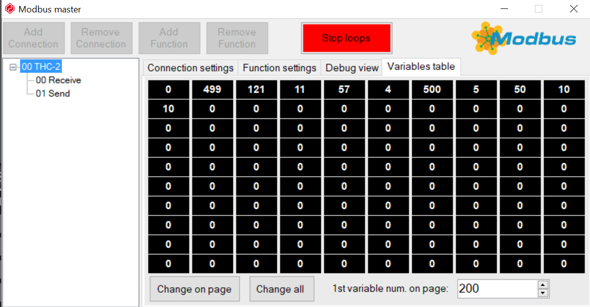
Step 2: Modbus Configuration.
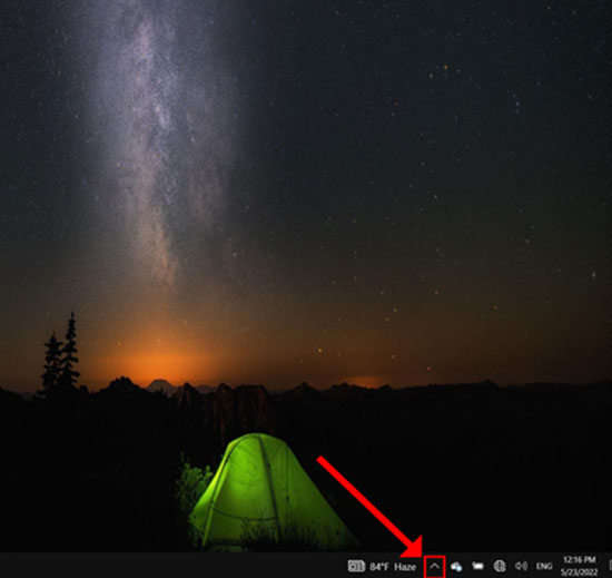
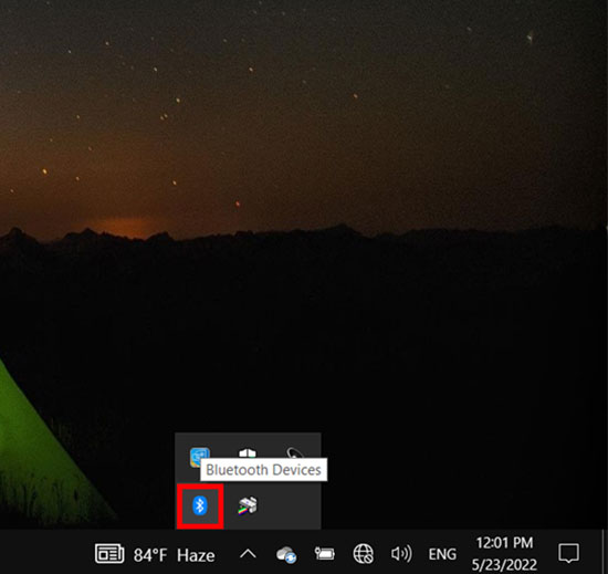
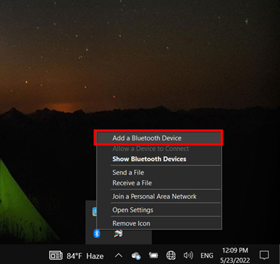
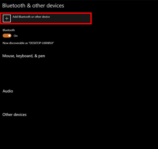
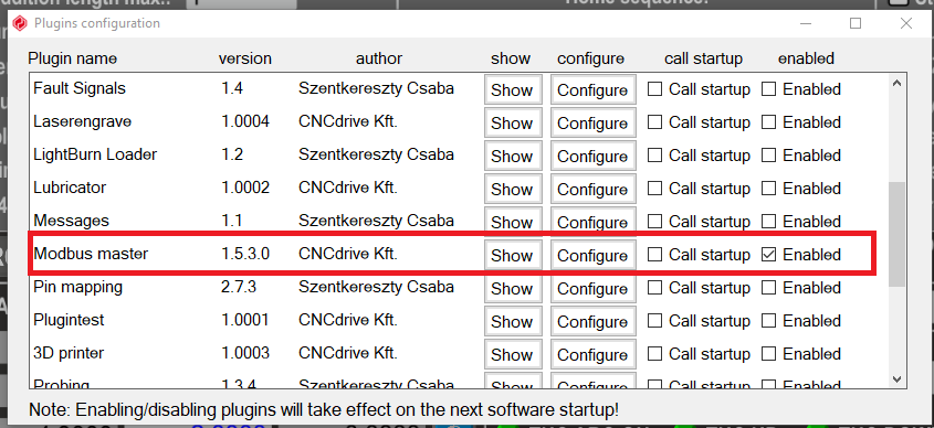
Enable Modbus Plugin
- Control Panel \ All Control Panel Items \ Devices and Printers
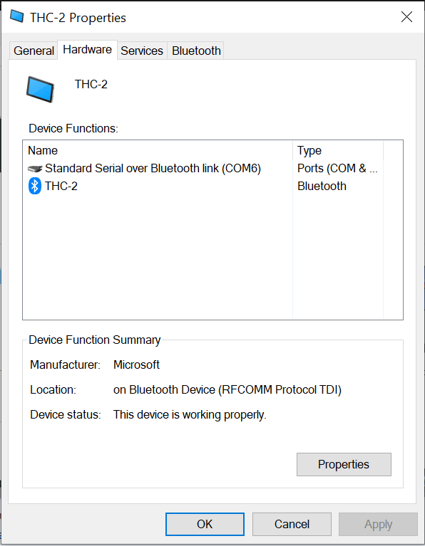
Note:
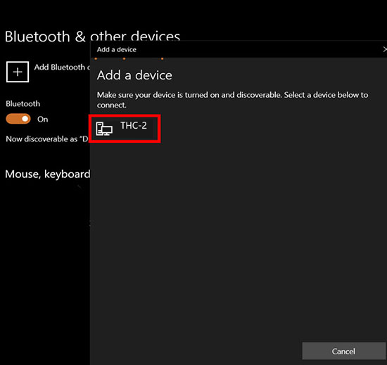
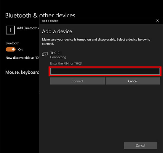
The COM port that Windows assigned, as would need to be set in the Modbus configuration.
Enable Modbus Plugin.
2. Screen Description.
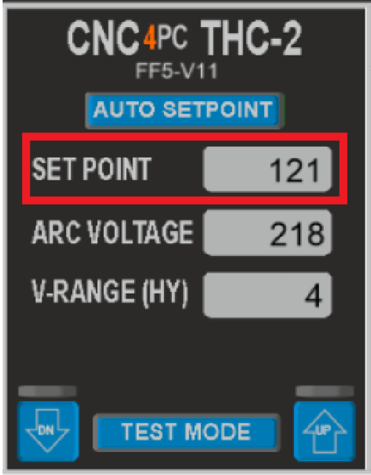
1. SETPOINT
It is the target voltage to be achieved.
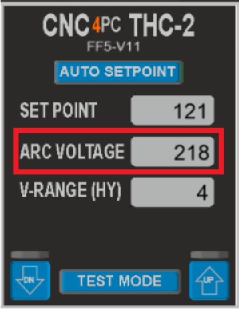
2. ARC VOLTAGE
Limit from 40 to 400VDC, True Voltage measured by the THC unit.
3. V-RANGE (HY)
It is the tolerance or (+/-) voltage range used to generate an adjustment. The torch height is not commanded to adjust if the true voltage is within the specified range. It can be between 2 to 32VDC

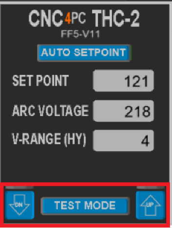
4. TEST MODE
The test mode simulates the plasma operation. It simulates the signals and you can observe how the controller reacts without having to power the plasma.
- Select the test mode button on the screen and the test led will turn on indicating the THC-2 is in test mode.
- Activating the DN or UP should make the Z-axis adjust. You can observe the signals received and the Z-axis adjusting accordingly.
- To exit test mode, Press the test mode button again.
- Z-axis correction will start after the DT seconds you set after the ACR OK signal is sensed.
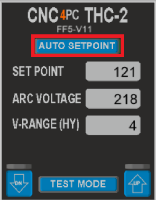
5. AUTO SETPOINT
| Automatically establishes the SetPoint based at the cutting height that is set. |
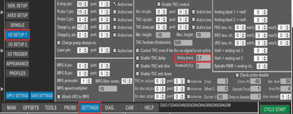
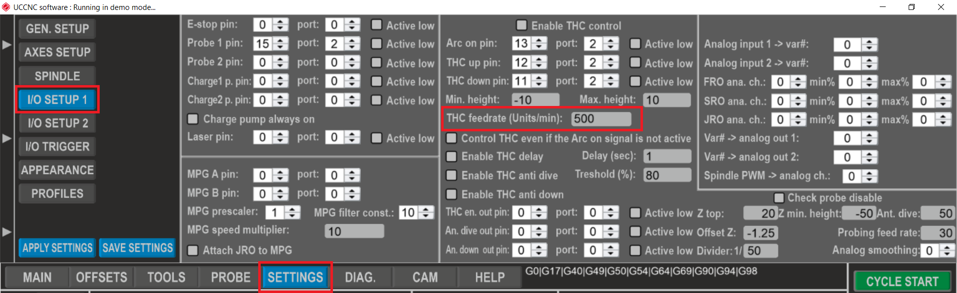
6. THC-DELAY
Torch motion starts the number of seconds you set as DT after the ARC signal is determined. This can be a value between 0.1 to 9.9 seconds. This is to allow the voltage to stabilize before adjusting the height.
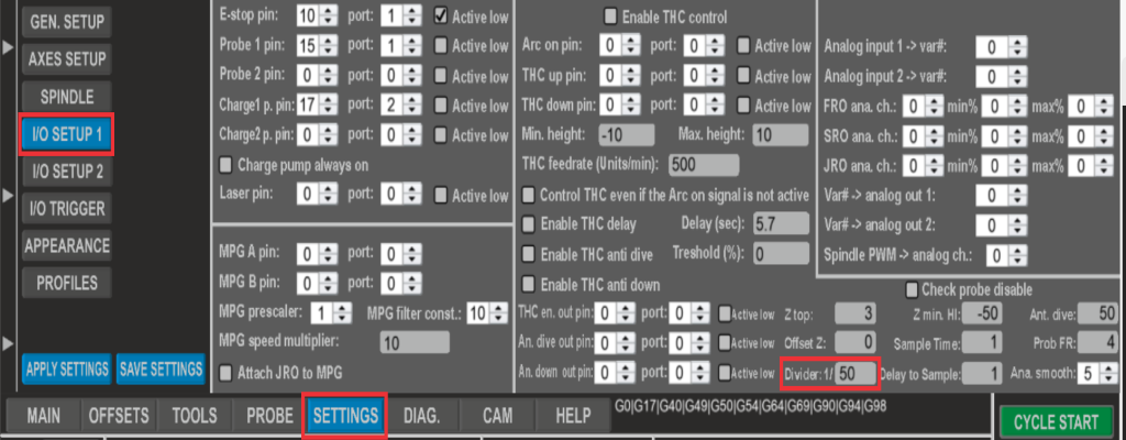
7. DIVIDER.
This is the divider ratio matching the one set in the plasma power supply. This can be a value between 1 to 100 select decimal values (finer resolution). This can also be used to fine-tune or calibrate the voltage reading.
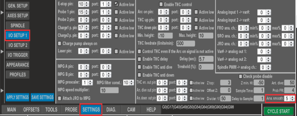
8. ANALOG SMOOTHING.
This data smoothest the voltage reading. This can be a value between 1 to 200. The analog voltage can be noisy or jumpy. This setting will allow for a more stable reading.
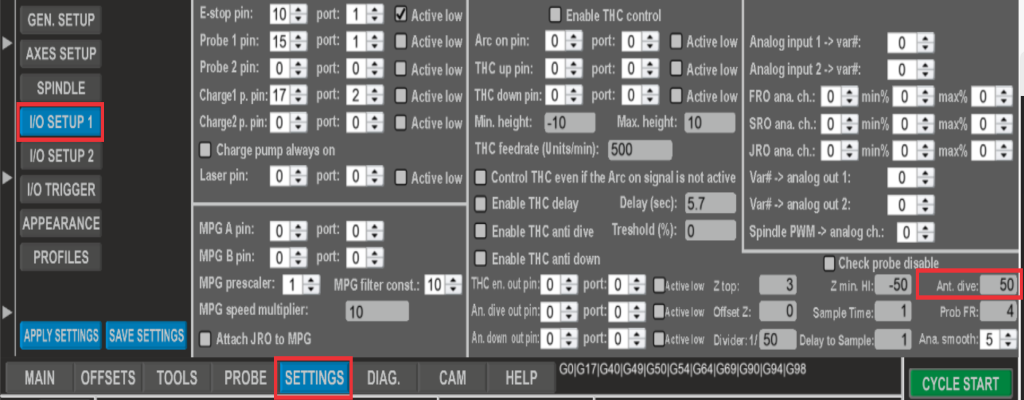
9. ANTI-DIVE
If the plasma torch moves over space, the THC will see it as a voltage spike. Setting a max value will allow the THC to ignore the voltage spike and prevent the torch from diving. This can be a value between 10 and 100 %.
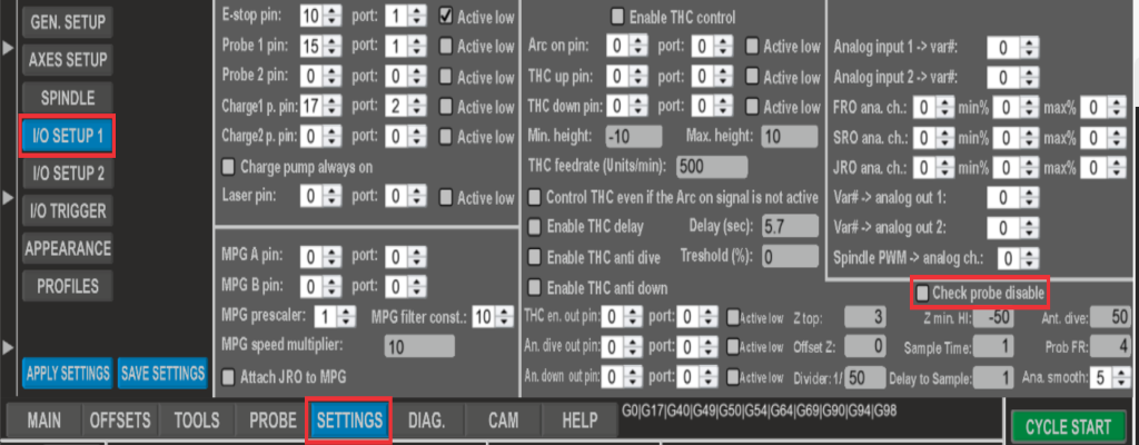
10. CHECK PROBE DISABLE
If enabled, the system will halt until the probe signal is no longer active. This will prevent the plasma from activating while the torch is probing (touching the material).
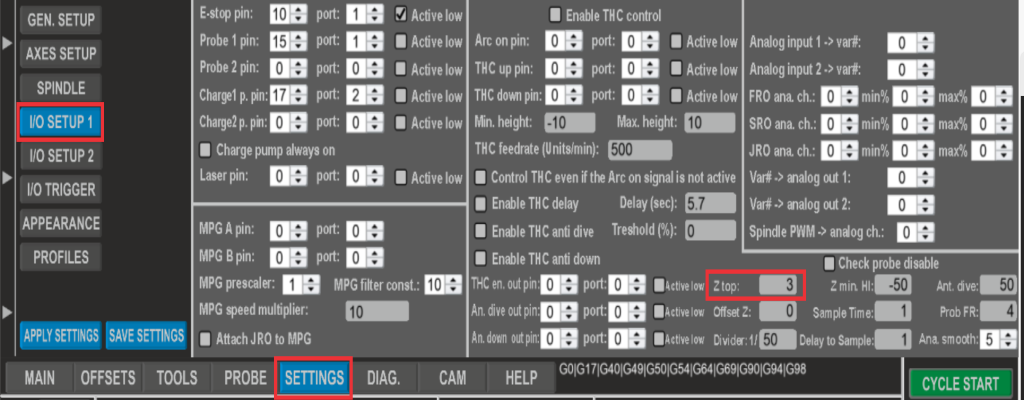
11. Z_TOP
Set Z_Top is the safe position from which rapid movements are allowed.
12. OFF SET_Z
This is an offset distance between the position of a switch and the material. This is used while probing and it is very useful when using Floating Heads which have a travel distance to the probing switch.

13. PROBING FEED RATE
It is the speed at which probing is executed.

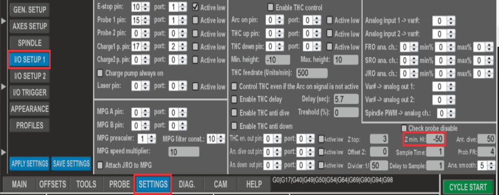
14. Z MIN. HEIGHT
Set how low you want the Z-axis to go while probing.
3. Calibration.
Recommendations:
- If the height adjustment is not smooth or overshoots the position, lower the % of correction speed.
- If you do not see action on the signals coming from the THC, try tracing them by measuring them at the output of the THC, the input of the breakout board, the LEDs of the breakout board, the Software Diagnostics, the software function, etc... You need to understand where you are losing them.
- The idea is that the correction is as fast as possible, but that it does not oscillate up and down. If it is set as too fast, you are going to find the Z axis moving like a sowing machine.
4. TEST.
Test the complete sequence which includes probing, piercing, and cutting with THC.
Configure the THC parameters according to the manual:
Command basic plasma THC operation to verify that everything is working correctly.
Feel free to adjust it to your units or other preferences.
5. Macros.
Test using the Macros
Macros:
Keep in mind the macro will now execute the following actions when M3 (Start Cutting) and M5 (End Cutting):
- If using a PTS-1 (Plasma Touch Sensor), the first section is to Enable the Probing action. You should see the ENABLE LED on the PTS-1 and also on the breakout board on the LED for the pin that you wired and configured for activating the probe. In these instructions, we are using Pin 1 on Port 2 (Output10).
- The Z-axis lowers until the nozzle or sensor that you connected to the nozzle touches the plate and closes the circuit and activates the probe input. You would momentarily see action for this on the TOUCH LED on the PTS-1 unit or the switch if using a Floating Head, on the LED for the input pin you assigned on the Breakout Board, and on the Probe LED on the Mach4 screen.
- As soon as probing is completed, the Probe ENABLE is disabled and the z-axis moves to the Pierce position or the Pierce Height that you configured.
- The plasma starts by activating the plasma relay and stays cutting for the duration of time that you configured or set as Pierce Time in Seconds.
- After pierce time the z-axis moves to the cut position that I set in the cut height.
- The Plasma stays on and continues to execute g-code and THC if implemented until an M5 is reached or e-stop is pressed.
Configure the operation parameters in this screen:
G code with macro:
6. Setting up the Post Processor.
Post for SheetCam:
- 12.1 UCCNC CNC4pc plasma no Z
- 12.2 UCCNC CNC4pc plasma with Z
www.cnc4pc.com/pub/media/productattachments/files/UCCNC CNC4pc plasma no Z
This post-processor works with all the data on the screen and uses the M32 and M52 macros.
https://www.cnc4pc.com/pub/media/productattachments/files/UCCNC CNC4pc plasma with Z
Load the postprocessor to be used: Select the "UCCNC CNC4pc plasma with Z" postprocessor in Options/Machine.
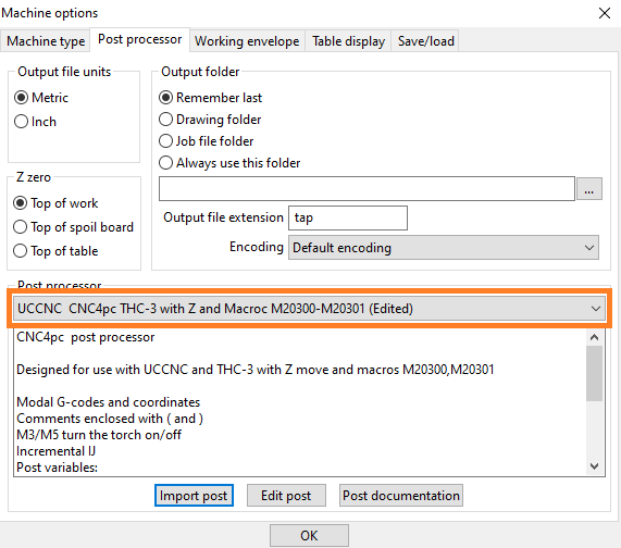
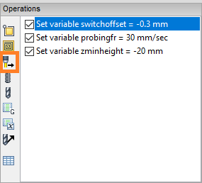
Click on "Set a post-processor variable".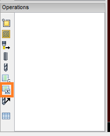
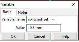
Enter the values of the variables to be used on probing: Steps 2 and 3 may need to be repeated for each variable. these can be: switchoffset (offset of the floating head switch), zminheight (how low the Z axis goes while probing), V_Range- set the range of setpoint, Set_Point- set the set point for the job, Auto_Setpoint - 0 disable auto set point and 1 enable auto set point, and probingfr (Velocity at which probing will be executed).
Create Cut Feature: After having entered all the variables, we proceed to do the cutting operation.