 ED
ED
C34DYN4 BOARD Rev.4
MARCH, 2019
Table of contents
1.0 OVERVIEW
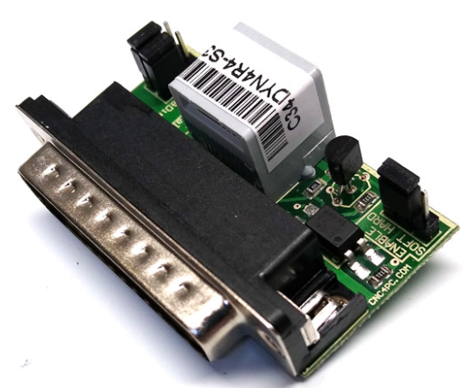
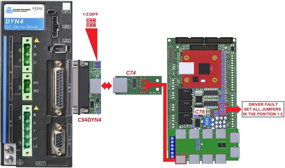
This board interface is used for the connection between C76, C82, C86ACORN, C86MASSO, C35S, and the DYN4 AC SERVO DRIVE.
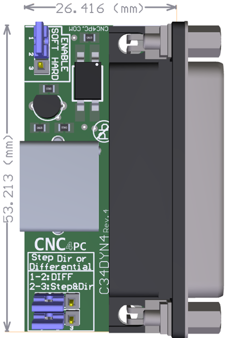
2.0 FEATURES
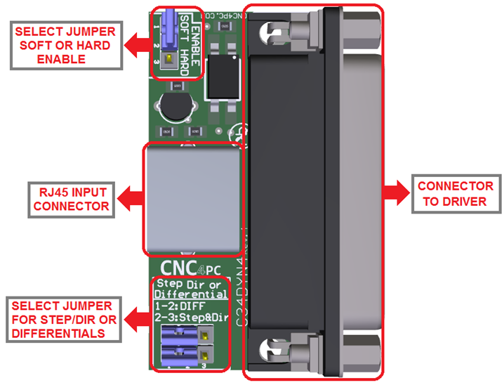
- DB25 Connector for Connecting Driver.
- RJ45 Connector for Axis.
- Select Jumper for Hardware Enable or Software Enable.
- Select Jumper for signals Differentials
3.0 BOARD DESCRIPTION
4.0 JUMPER TO SELECT THE ENABLE
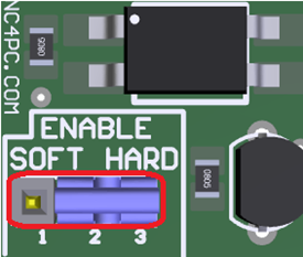
Use
Software Enable to keep the driver active only while the system is active.
Set
of jumpers as shown in the image.
SOFT ENABLE
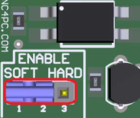
Use Hardware Enable to keep the driver enabled at all times.
A set of jumpers as shown in the image.
HARD ENABLE
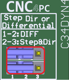
JUMPER TO SELECT THE DIFFERENTIAL
When working with the STEP and DIR inputs as differential signals, you must use the board and set the jumper as shown in the image.
DIFERENTIAL.
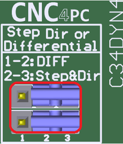
If not, use the differential signal for STEP & DIR, set the jumper as shown in the image.
STEP & DIR
5.0 PINOUT
DYN4 SERVO DRIVE AND C34DYN4 CONNECTION
|
DB25 PIN |
FUNCTION |
RJ45 PIN |
|
15 |
SERVO ENABLE * |
5 |
|
18 |
ALARM * |
5 |
|
10 |
DIR- |
3 |
|
22 |
DIR+ |
6 |
|
23 |
STEP- |
1 |
|
11 |
STEP+ |
2 |
|
1 |
DIGITAL INPUT COMMON GROUND |
Internally routed |
|
4 |
Int. 14VDC input |
Wired to pin 17 |
|
17 |
Int. 14VDC output |
Wired to pin 4 |
Note:
* Servo ENABLE and Alarm signals are related to the RJ45 pin 5 of the C34YN4 board, but they are not connected directly to this pin.
6.0 WIRING SAMPLE
6.1 Diagram of connection with input signals Step & Dir and C82.
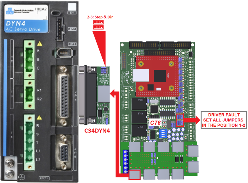
6.1 Diagram of connection with input signals Step & Dir and C82.
7.0 DIMENSIONS